Download

1 / 18
380 likes | 1.05k Views
Design of Mat/Raft Foundation. Mat or raft foundation is a large concrete slab supporting several columns in two or more rows. It is used where the supporting soil has low bearing capacity.

E N D
Mat or raft foundation is a large concrete slab supporting several columns in two or more rows. • It is used where the supporting soil has low bearing capacity. • The bearing capacity increased by combining all individual footings in to one mat –since bearing capacity is proportional to width and depth of foundations. • In addition to increasing the bearing capacity, mat foundations tend to bridge over irregularities of the soil and the average settlement does not approach the extreme values of isolated footings. • Thus mat foundations are often used for supporting structures that are sensitive to differential settlement.
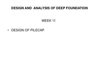
Design of uniform mat • Design Assumptions • mat is infinitely rigid • planner soil pressure distribution under mat • Design Procedure • Determine the line of action of the resultant of all the loads acting on the mat • Determine the contact pressure distribution as under • If the resultant passes through the center of gravity of the mat, the contact pressure is given by
If the resultant has an eccentricity of ex and ey in the x and y direction The maximum contact pressure should be less than the allowable soil pressure • Divide the slab mat into strips in x and y directions. Each strip is assumed to act as independent beam subjected to the contact pressure and the columns loads. • Determine the modified column loads • Draw the shear force and bending moment diagrams for each strip. • Select depth of mat for shear requirement • Select steel reinforcement for moment requirement
Y ex ey X X Y
Example • A mat foundation is to be design by the conventional method (rigid method) for the loadings shown in Fig. below. • All columns are 40X40cm • Ultimate soil bearing pressure , qult = 100kPa • fyk = 300MPa fyd = 300/1.15 = 260.87 Mpa • C25 fck= 20MPafctk = 1.5 MPa,
X 600kN 750kN 600kN 6m 1800kN 1320kN 1800kN 6m 1800kN 1320kN 1800kN 6m Y 600kN 750kN 600kN 5m 5m
Location of c.g. of loads • P = (600 +750+ 600)*2 +(1800+1800+1320)*2 =13740kN • 13740 X = (750 +1800+1800+750)*5 + (600 +1320+1320+600)* 10 X = 4.65m ex = 5-4.65 = 0.35 X’ = 5 +0.35 = 5.35m • B min = 2*( 5.35 +0.20+0.15 ) =11.40m • 13740 Y = (600 +750+600)*18 + (1800 +1800+1320)* 12 + (1800 +1800+1320)* 6 Y = 9m ey = 6+ 6/2 -9 = 0 • Lmin = 2* (9+0.20+0.15) = 18.70m • Dimension of Mat 11.40 X 18.70m
Actual contact pressure = P/(BL) = 13740/(11.40*18.70) =64.45kPa < ult = 100kPa • Thickness of the mat • Punching shear • Punching shear under 1800kN load Take d= 0.70m and = min = 0.50/fyk = 0.50 /300 = 0.0017 k1 = ( 1+50) = (1 +50*0.0017) =1.085 k2 = 1.6 – d =1.6 -0.70 = 0.90 , Take K2 =1 Pr =(0.85+0.4+1.105)2+(0.4+3(0.70) =7.21m • Net shear force developed • Vd= 1800 -*(2.355* 2.50), =64.45kP • Vd= 1800 -64.45*(2.355* 2.50)=1420.55kN 40 0.4+3d 40 1.5d=1.105>0.85 1.5d
Punching shear resistance Vup = 0.25fctd k1k2ud (MN) • Vup = 0.25 *1000* 1.085*1.00*7.21*0.70 =1369.00kN < Vd .. NOTOK! Increase the depth Take d= 0.75m and = min = 0.50/fyk = 0.50 /300 = 0.0017 k1 = ( 1+50) = (1 +50*0.0017) =1.085 k2 = 1.6 – d =1.6 -0.75 = 0.85 , Take K2 =1 Pr =(0.85+0.4+1.125)2+(0.4+3(0.75) =7.40m • Net shear force developed • Vd= 1800 -*(2.375* 2.65), =64.45kP • Vd= 1800 -64.45*(2.375* 2.65)=1394.37kN
Punching shear resistance Vup = 0.25fctd k1k2ud (MN) • Vup = 0.25 *1000* 1.085*1.00*7.40*0.75 =1505.44kN >Vd .. OK! • Check punching shear under 1320kN Pr =(1.125 +0.15+0.4)2+(0.4+3(0.75)) =6.00m • Net shear force developed • Vd= 1320 -64.45*(1.675*2.65)=1033.92kN • Punching shear resistance Vup = 0.25fctd k1k2ud (MN) • Vup = 0.25 *1000* 1.085*1.00*6.00*0.75 =1220.63kN > Vd .. OK! 0.4+3d 40 40 0.15 1.5d=1.125
1.5d=1.125 • Check punching shear under 600kN • Pr =(1.125+0.15+0.4) +(1.125+0.15+0.4) =3.35m • Net shear force developed • Vd= 600 -64.45*(1.675*1.675)=419.18kN • Punching shear resistance Vup = 0.25fctd k1k2ud (MN) • Vup = 0.25 *1000* 1.085*1.00*3.35*0.75 =681.52kN > Vd .. OK! 40 0.15 40 1.5d=1.125 0.15
2.85m 3.55m 5.00m 3.35m Strip 4 • Soil reaction analysis:- Divide the slab mat into strips in x and y directions 6.00m Strip 3 6.00m Strip 2 3.35m Strip 1 Strip A Strip C Strip B
Strip A, (64.45)*3.55 = 228.80kN/m • Strip B , (64.45)*5.00 = 322.25kN/m • Strip C, (64.45)*2.85 = 183.68kN/m • Strip 1 &Strip 4, (64.45)*3.35 = 215.91kN/m • Strip 2 & Strip 3 (64.45)*6.00 = 386.70kN/m • Shear force and Bending moment diagrams for each strip • Strip A 600kN 600kN 1800kN 1800kN 228.80kN/m 0.35 6.00 6.00 6.00 0.35
R = 228.80* 18.70 =4278.56kN • V = P- R = 4800-4278.56 =521.44 0 • Hence take average of P and R • I.e., (4800 +4278.56 )/2 =4539.28kN • avg = (4539.28)/18.70 =242.74kN/m • P1avg = P4avg = (4539.28/4800) *600 =567.41kN • P2avg = P3avg = (4539.28/4800) *1800 =1702.23kN
567.41kN 567.41kN 1702.23kN 1702.23kN 242.74kN/m 0.35 6.00 6.00 6.00 0.35 973.99kN 1.99m 728.24N 482.45kN 3.00m 4.01m 84.96kN SFD 84.96kN 482.45kN 464.57kN-m 464.57kN-m 728.24kN 397.09kN-m 973.99kN BMD 14.87kN-m 14.87kN-m 1489.48kN-m 1489.48kN-m
600kN 600kN 750kN • Strip 1 &Strip 4, (64.45)*3.35 = 215.91kN/m • R = 215.91* 11.40=2461.37kN • V = P- R = 1950-2461.37 = -511.37 0 • Hence take average of P and R • I.e., (1950+2461.37 )/2 =2205.69kN • avg = (2205.69)/11.40 =193.48kN/m • P1avg = P3avg = (2205.69/1950) *600 =678.67kN • P2avg = (2205.69/1950) *750 =848.34kN 215.910kN/m 1.05 5.00 0.35 5.00
678.67kN 678.67kN 848.34kN 491.88kN 610.94kN 193.48kN/m 1.84m 2.46m 1.05 5.00 203.15kN 0.35 5.00 SFD 67.73kN 356.46kN 475.52kN 477.68kN-m 180.78kN-m BMD 11.85kN-m 147.56kN-m 106.66kN-m