Download
1 / 78
1.46k likes | 2.77k Views
SYSTEM SOFTWARE. CS2304. Dr.A.KANNAN, PROFESSOR & HEAD, DEPARTMENT OF IST. UNIT I INTRODUCTION. UNIT II ASSEMBLERS. UNIT III LOADERS AND LINKERS. UNIT IV MACRO PROCESSORS. UNIT V SYSTEM SOFTWARE TOOLS. INTRODUCTION.

E N D
SYSTEM SOFTWARE CS2304 Dr.A.KANNAN, PROFESSOR & HEAD, DEPARTMENT OF IST
UNIT I INTRODUCTION UNIT II ASSEMBLERS UNIT III LOADERS AND LINKERS UNIT IV MACRO PROCESSORS UNIT V SYSTEM SOFTWARE TOOLS
INTRODUCTION • System software and machine architecture • The Simplified Instructional Computer (SIC) • Machine architecture • Data and instruction formats • Addressing modes • Instruction sets • I/O and programming
SYSTEM SOFTWARE • The subject introduces the design and implementation of system software • System software consists of a variety of programs that support the operation of a computer • Operating system, compiler, assembler, macro processor, loader or linker, debugger, text editor, database management systems, software engineering tools, ….
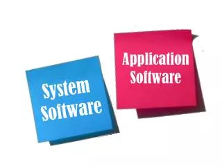
SOFTWARE ITS CLASSIFICATION • Software is set of instructions or programs written to carry out certain task on digital computers • Classified into system software and application software • System software consists of a variety of programs that support the operation of a computer • Application software focus on an application or problem to be solved
THIS CHAPTER GIVES YOU… • System Software & Machine Architecture • The Simplified Instructional Computer SIC and SIC/XE • Traditional (CISC) Machines • Complex Instruction Set Computers • RISC Machines • Reduced Instruction Set Computers
SYSTEM SOFTWARE & MACHINE ARCHITECTURE • Machine Dependent • Machine Independent
MACHINE INDEPENDENT • There are aspects of system software that do not directly depend upon the type of computing system • general design and logic of an assembler • general design and logic of a compiler • code optimization techniques
MACHINE DEPENDENT • System software – support operation and use of computer • Application software - solution to a problem • Assembler translate mnemonic instructions into machine code • Compilers must generate machine language code
THE SIMPLIFIED INSTRUCTIONAL COMPUTER (SIC) • SIC is a hypothetical computer that includes the hardware features most often found on real machines • Two versions of SIC • standard model (SIC) • extension version (SIC/XE) • (extra equipment or extra expensive)
SIC MACHINE ARCHITECTURE • Memory and Registers • Data Formats • Instruction Formats • Addressing Modes • Instruction Set • Input and Output
MEMORY • 215 bytes in the computer memory • 32,768 bytes • Uses Little Endian • 3 consecutive bytes form a word • 8-bit bytes
DATA FORMATS • Integers are stored as 24-bit binary numbers • 2’s complement representation is used for negative values • No floating-point hardware
x address (15) opcode (8) INSTRUCTION FORMATS
INSTRUCTION SET • load and store: • LDA, LDX, STA, STX, etc. • integer arithmetic operations: • ADD, SUB, MUL, DIV, etc. • All arithmetic operations involve register A and a word in memory, with the result being left in the register
INSTRUCTION SET • comparison: • COMP - compares the value in register A with a word in memory, this instruction sets a condition code CC to indicate the result
INSTRUCTION SET • Conditional jump instructions: • JLT, JEQ, JGT • These instructions test the setting of CC and jump accordingly
INSTRUCTION SET • subroutine linkage: JSUB, RSUB • JSUB jumps to the subroutine, placing the return address in register L • RSUB returns by jumping to the address contained in register L
INPUT AND OUTPUT • Input and Output are performed by transferring 1 byte at a time to or from the rightmost 8 bits of register A (accumulator) • The Test Device (TD) instruction tests whether the addressed device is ready to send or receive a byte of data • Read Data (RD), Write Data (WD)
DATA MOVEMENT • 3-byte word: • LDA, STA, LDL, STL, LDX, STX • A- Accumulator, L – Linkage Register, X – Index Register • 1-byte: LDCH, STCH • No memory-memory move instruction
STORAGE DEFINITION • WORD - ONE-WORD CONSTANT • RESW - ONE-WORD VARIABLE • BYTE - ONE-BYTE CONSTANT • RESB - ONE-BYTE VARIABLE
EXAMPLE PROGRAMS (SIC) Example 1 LDA FIVE STA ALPHA LDCH CHARZ STCH C1 . ALPHA RESW 1 FIVE WORD 5 CHARZ BYTE C’Z’ C1 RESB 1
EXAMPLE PROGRAMS (SIC) Example 2 LDA ALPHA ADD INCR SUB ONE STA BEETA ONE WORD 1 ALPHA RESW 1 BEETA RESW 1 INCR RESW 1 All arithmetic operations are performed using register A, with the result being left in register A.
SIC/XE MACHINE ARCHITECTURE • Memory • Maximum memory available on a SIC/XE system is 1 Megabyte (220 bytes) • Registers • Additional B, S, T, and F registers are provided by SIC/XE
FLOATING-POINT DATA TYPE • There is a 48-bit floating-point data type F*2(e-1024)
INSTRUCTION FORMATS Format 1 (1 byte) Format 2 (2 bytes) Formats 1 and 2 are instructions do not reference memory at all
CONTINUED… Format 3 (3 bytes) Format 4 (4 bytes)
ADDRESSING MODES & FLAG BITS • e - e = 0 means format 3, e = 1 • means format 4 • Bits x,b,p: Used to calculate the target address using relative, direct, and indexed addressing • Modes • Bits i and n: Says, how to use the target address
ADDRESSING MODES Format 3
FLAG BITS CONTINUED… • b and p - both set to 0, disp field from format 3 instruction is taken to be the target address. For a format 4 bits b and p are normally set to 0, 20 bit address is the target address • x - x is set to 1, X register value is added for target address calculation
FLAG BITS CONTINUED… Format 3 or 4 • i=1, n=0 Immediate addressing, TA: TA is used as the operand value, no memory reference • i=0, n=1 Indirect addressing, ((TA)): The word at the TA is fetched. Value of TA is taken as the address of the operand value • i=0, n=0 or i=1, n=1 Simple addressing, (TA):TA is taken as the address of the operand value
INSTRUCTION SET • Instructions to load and store the new registers LDB, STB, etc. • Floating-point arithmetic operations • ADDF, SUBF, MULF, DIVF • Register move instruction : RMO • Register-to-register arithmetic operations • ADDR, SUBR, MULR, DIVR • Supervisor call instruction : SVC
INPUT AND OUTPUT • There are I/O channels that can be used to perform input and output while the CPU is executing other instructions • Allows overlap of computing and I/O, resulting in more efficient system operation • The instructions SIO, TIO, and HIO are used
EXAMPLE PROGRAMS (SIC/XE) LDA #5 STA ALPHA LDA #90 STCH C1 . . ALPHA RESW 1 C1 RESB 1 Example 1
EXAMPLE PROGRAMS (SIC/XE) Example 2 LDS INCR LDA ALPHA ADD S,A SUB #1 STA BEETA …….. ………….. ALPHA RESW 1 BEETA RESW 1 INCR RESW 1 All arithmetic operations are performed using register A, with the result being left in register A.
DIFFERENT ARCHITECTURES • Traditional (CISC) machines • - VAX Architecture • - Pentium Pro Architecture • RISC machines • - UltraSPARC Architecture • - Cray T3E Architecture
COMPARISON OF THESE • Memory • Registers • Data Formats • Instruction Formats • Addressing Modes • Instruction Set • Input and Output
TRADITIONAL (CISC) MACHINES • Complex Instruction Set Computers • Has relatively large and complex instruction set • Different instruction formats, different lengths, different addressing modes • Implementation of hardware is complex • VAX and Intel x86 processors are examples
VAX ARCHITECTURE • Memory - The VAX memory consists of 8-bit bytes. All addresses used are byte addresses. • Two consecutive bytes form a word, Four bytes form a longword, eight bytes form a quadword, sixteen bytes form a octaword. • All VAX programs operate in a virtual address space of 232 bytes , One half is called system space, other half process space
REGISTERS • 16 GPRs, 32 bits each, R0 to R15, PC (R15), SP (R14), Frame Pointer FP ( R13), Argument Pointer AP (R12) ,Others available for general use • Process status longword (PSL) – for flags
DATA FORMATS • Integers are stored as binary numbers in byte, word, longword, quadword, octaword • 2’s complement for negative numbers • Characters 8-bit ASCII codes • Four different floating-point data formats
INSTRUCTION FORMATS • Uses variable-length instruction formats – op code 1 or 2 bytes, maximum of 6 operand specifiers depending on type of instruction • Tabak – Advanced Microprocessors (2nd edition) McGraw-Hill, 1995
ADDRESSING MODES • VAX provides a large number of addressing modes • Register mode, register deferred mode, autoincrement, autodecrement, base relative, program-counter relative, indexed, indirect, immediate
INSTRUCTION SET • Symmetric with respect to data type - Uses prefix – type of operation, suffix – type of operands, a modifier – number of operands • ADDW2 - add, word length, 2 operands, MULL3 - multiply, longwords, 3 operands CVTCL - conversion from word to longword • VAX provides instructions to load and store multiple registers
INPUT AND OUTPUT • Uses I/O device controllers • Device control registers are mapped to separate I/O space • Software routines and memory management routines are used
PENTIUM PRO ARCHITECTURE • Introduced by Intel in 1995 • Memory - consists of 8-bit bytes, all addresses used are byte addresses. Two consecutive bytes form a word, four bytes form a double word (dword) • Viewed as collection of segments - address = segment number + offset • code, data, stack , extra segments
REGISTERS • 32-bit, eight GPRs, EAX, EBX, ECX, EDX, ESI, EDI, EBP, ESP • EAX, EBX, ECX, EDX – are used for data manipulation, other four are used to hold addresses • EIP – 32-bit contains pointer to next instruction to be executed • FLAGS – 32 - bit flag register • CS, SS, DS, ES, FS, GS – Six 16-bit segment registers
DATA FORMATS • Integers – 8, 16, or 32 bit binary numbers • 2’s complement for negative numbers • BCD is also used – unpacked BCD, packed BCD • There are three floating point data formats – single, double, and extended-precision • Characters – one per byte – ASCII codes