Download
1 / 21
210 likes | 378 Views
Laser-wire Measurement Precision. Grahame Blair Beijing- BILCW07, 6 th February 2007. Introduction Overview of errors Ongoing technical work in this area Plans for the future. Laser-wire People. BESSY: T. Kamps

E N D
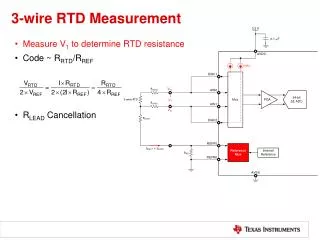
Laser-wireMeasurementPrecision Grahame Blair Beijing- BILCW07, 6th February 2007 • Introduction • Overview of errors • Ongoing technical work in this area • Plans for the future.
Laser-wire People BESSY: T. Kamps DESY : E. Elsen, H. C. Lewin, F. Poirier, S. Schreiber, K. Wittenburg, K. Balewski JAI@Oxford: B. Foster, N. Delerue, L. Corner, D. Howell, M. Newman, A. Reichold, R. Senanayake, R. Walczak JAI@RHUL: G. Blair, S. Boogert, G. Boorman, A. Bosco, L. Deacon, P. Karataev, S. Malton , M. Price I. Agapov (now at CERN) CCLRC: I. Ross KEK: A. Aryshev, H. Hayano, K. Kubo, N. Terunuma, J. Urakawa SLAC: A. Brachmann, J. Frisch, M. Woodley FNAL: M. Ross
Laser-wire Principle • PETRAII • 2d scanning system • DAQ development • Crystal calorimeter • → PETRA III • Ultra-fast scanning • Diagnostic tool
The Goal: Beam Matrix Reconstruction • 50% Reconstruction success • <5% error on σy NOTE: Rapid improvement with better σy resolution Reconstructed emittance of one train using 1% error on σy Conclude: Essential to measure the spot-size at the few % level or better I. Agapov, M. Woodley
y u x Skew Correction ILC LW Locations Eb = 250 GeV Error on coupling term:
2σL=2cτL Scan of an ILC Train of Bunches αtrainσe 2σe 2αJσe 2σscan Ntrain bunches 2σe (1 + strain) Not to scale!
Need for Intra-Train Scanning For <0.5% effect, strain<0.12; otherwise, the effect must be subtracted For 1m bunches, the error after subtracting for any systematic shift (assumed linear ±αtrainalong the train) is: For <0.5% effect, αtrain<2.6; otherwise, higher precision BPMs required
Machine Contributions to the Errors Bunch Jitter Dispersion BPM resolution of 20 nm may be required Assuming can be measured to 0.1%, then must be kept < ~ 1mm
Alternative Scan Mode • R&D currently investigating ultra-fast scanning (~100 kHz) • using Electro-optic techniques • Alternative: Keep laser beam fixed and use natural beam jitter • plus accurate BPM measurements bunch-by-bunch. • Needs the assumption that bunches are pure-gaussian • For one train, a statistical resolution of order 0.3% may be possible Single-bunch fit errors for BPM resolution fixed at 100 nm Beam jitter fixed at 0.25σ
√2σℓ laser beam xR σey σex σℓ electron bunch Laser Conventions For TM00 laser mode:
Compton Statistics Approximate – should use full overlap integral (as done below…) Where : Compton xsec factor e-bunch occupancy Laser wavelength Laser peak power Detector efficiency (assume Cherenkov system)
TM00 Mode Overlap Integrals Rayleigh Effects obvious • Main Errors: • Statistical error from fit ~ -1/2 • Normalisation error (instantaneous value of ) – assume ~1% for now. • Fluctuations of laser M2 – assume M2 known to ~1% • Laser pointing jitter
TM01 Y. Honda et al TM01 gives some advantage for larger spot-sizes Estat EM2 TM00 TM01 TM01 TM00
Laser Requirements ILC-spec laser is being developed at JAI@Oxford based on fiber amplification. L. Corner et al
ATF2 LW; aiming initially at f2; eventually f1? TM00 mode Statistical Error From 19-point scan • Optimal f-num1-1.5 for = 532nm • Then improve M2 determination • f-2 lens about to be installed at ATF Relative Errors Error resulting from 5% M2 change
Towards a 1 m LW preliminary Resultant errors/10-3 Goals/assumptions Final fit, including dispersion Could be used for measurement → E
Lens Design + Tests • f-2 lens has been built and is currently under test. • Installation at ATF planned for this year M. Newman, D. Howell et al. Designs for f-1 optics are currently being studied, including: Aspheric doublet Vacuum window N. Delerue et al.
ATF Ext S. Boogert, L. Deacon
ATF/ATF2 Laser-wire • At ATF2, we will aim to measure micron-scale electron spot-sizes with green (532 nm) light. • Two locations identified for first stage (more stages later) • 0.75m upstream of QD18X magnet • 1m downstream of QF19X magnet LW-IP (1) LW-IP (2) σx = 38.92 m σx = 142.77 m σy= 7.74 m σy = 7.94 m Nominal ATF2 optics ATF2 LW-test optics LW-IP (1) LW-IP (2) σx = 20.43 mσx = 20 m σy= 0.9 m σy = 1.14 m P. Karataev Ideal testing ground for ILC BDS Laser-wire system
ATF LW Plans • March 07: Start upgrading ATF LW hardware • April 07: aim to install f2 lens system • May/Jun 07: aim to take first micron-scale scans Longer term • Upgrade laser system to reduce spot-size further • Install additional LW systems, building towards emittance measurement system for ATF2. • Investigate running with UV light. • Implement ultra-fast scanning system (first to be tested at PETRA, funding permitting) • Build f-1/1.5 optical system
Summary • Very active + international programme: • Hardware • Optics design • Advanced lasers • Emittance extraction techniques • Data taking + analysis • Simulation • All elements require R&D • Laser pointing • M2 monitoring • Low-f optics • Fast scanning • High precision BPMs • Look forward to LW studies at PETRA and ATF • ATF2 ideally suited to ILC-relevant LW studies.