Download
1 / 19
190 likes | 351 Views
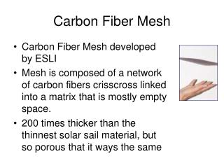
Ultra-light carbon fiber structures: evaporative tests. Claudio BORTOLIN (CERN) Martin DOUBEK ( CTU, Czech Technical University, Prague ) Andrea FRANCESCON ( CERN ) Manuel GOMEZ MARZOA (CERN) Romualdo SANTORO (CERN) 4 th September 2012. Contents. Heater analysis

E N D
Ultra-light carbon fiber structures: evaporative tests Claudio BORTOLIN (CERN) Martin DOUBEK (CTU, Czech Technical University, Prague) Andrea FRANCESCON (CERN) Manuel GOMEZ MARZOA (CERN) RomualdoSANTORO (CERN) 4th September 2012 ALICE Cooling Meeting - 4th September 2012
Contents • Heater analysis • NTCs vs. thermographic picture analysis • Single-phase water tests: D08 prototype • Evaporative tests: D08 prototype • Comparison with water single-phase tests • Temperature distribution • Conclusion • Prototype and test facility optimization ALICE Cooling Meeting - 4th September 2012
Heater power distribution analysis • The D06 prototype with single-phase water tests: presented at WG4 Meeting the 27th July 2012 • Two warmer regions were seen towards the centre of the stave at the sides. • Possible causes: • Lack of thermal contact plate-heater • Manufacturing difficulties • Gluing defects • Heater power dissipation maldistribution? 8 L min-1, 0.5 W cm-2 • A single heater and the D04 prototype heater will be powered up: • Check temperature distribution • Deviation of measurements thermocamera/NTCs ALICE Cooling Meeting - 4th September 2012
Heater power distribution analysis 3 1 2 3 1 2 3 2 1 • *ΔT-n = Average_T_NTC – Average_T_ThermoPic ALICE Cooling Meeting - 4th September 2012
Heater power distribution analysis 3 2 1 3 1 2 3 2 1 • *ΔT-n = Average_T_NTC – Average_T_ThermoPic ALICE Cooling Meeting - 4th September 2012
D08 prototype: description IN OUT ALICE Cooling Meeting - 4th September 2012
D08 prototype: water tests ALICE Cooling Meeting - 4th September 2012
D08 prototype: water tests • Temperature along stave: D08, 8 L min-1, 0.3 W cm-2 • Assuming same power density across stave, D08 performs better than D04 • Cannot cool at 0.5 W cm-2 and needs optimization ALICE Cooling Meeting - 4th September 2012
Water tests: conclusion ALICE Cooling Meeting - 4th September 2012
D08 2-phase C4F10 tests @DSF • Inlet vapor quality: • Superheating at stave outlet: T = const x = const • Mass flow rate calculation: 1 p [bar] where L is latent heat [kJ kg-1]: 3 3’ 2 4 Qstave[W] • Usually: h [kJ kg-1] ALICE Cooling Meeting - 4th September 2012
D08: water vs. C4F10 @0.3 W cm-2 Evaporative cooling system performs as good as single-phase water ALICE Cooling Meeting - 4th September 2012
D08: water vs. C4F10 @0.5 W cm-2 • Good selection of mass flow rates and agreement between thermographic pictures and NTCs over the heater. • Knowing the vapor quality at the outlet is very important. ALICE Cooling Meeting - 4th September 2012
D08: C4F10 tests discussion • Two cases did not perform as expected: • Low vapor quality at the stave entrance: saturated liquid entering stave? • Low vapor quality at stave outlet: single phase flow? • Low vapor quality at the stave entrance: saturated liquid entering stave? • Mass flow rate too low: superheated vapor at stave outlet ALICE Cooling Meeting - 4th September 2012
Conclusion • Almost the same cooling performance is achieved with single-phase water cooling circuit as when using evaporative C4F10 for the same prototype. • There is not a big increase of the HTC wall-fluid using evaporative C4F10 • ΔT wall-water: through the HTC, establishes the margin of improvement by using a better cooling system for this setup: • C4F10, two-phase: • Water, single phase: Evaporative C4F10 means CFD Simulations ALICE Cooling Meeting - 4th September 2012
Optimization lines • Stave optimization: • Pipe inner diameter: can be smaller than 1.5 mm (but less contact area!) • More rigid piping: PEEK (avoid deformations, pinching, ensure contact) • D08 prototype shows no better thermal performance with evaporative flow • Improve weak parts of model (thermal contact, gluing…) • Structure thermal analysis/simulation helpful • Avoid connectors: leaks, extra pressure drop. • Proposal: single pipe w/ 180 deg elbow. • In/Out connector: select useful pipe diameter. • Setup optimization: • A by-pass will be added to the circuit in DSF in order to be able to work with smaller mass flow rates (especially microchannel) • For this reason, a coriolisflow meter will be moved in DSF • Need for subcooled liquid before the flow meter! • Sensors calibration (see backup slide). ALICE Cooling Meeting - 4th September 2012
Ultra-light carbon fiber structures: evaporative tests Claudio BORTOLIN (CERN) Martin DOUBEK (CTU, Czech Technical University, Prague) Andrea FRANCESCON (CERN) Manuel GOMEZ MARZOA (CERN) RomualdoSANTORO (CERN) 4th September 2012 ALICE Cooling Meeting - 4th September 2012
Backup D08: C4F10 tests discussion • Where; • Subcooling = TSAT@p1 – T1 (entrance of stave). • T3’: saturation temperature at p=p3. Used to calculate superheating at the stave outlet (if superheated vapor present). • Error in temperature measurement at point 3: calculated as ε = T3-T3’ ALICE Cooling Meeting - 4th September 2012
Backup An estimation of the uncertainty of measurements: • At point 3, calculate h for saturated liquid and vapor using p3. With p3 and T3, the point is superheated vapor and h3 can be calculated. If temperature measurement was fine, , and: • In the real case, x3 > 1. The deviation is the % of total error resulting frpm measuring p, T and calculating the enthalpies (RefProp). ALICE Cooling Meeting - 4th September 2012
Backup An estimation of the uncertainty of measurements: • At point 3, vapor quality at the stave outlet (calculated using an energy balance) indicates that the fluid is in the the two-phase region. If that is the case, then: • However, a is read instead. The difference remains stable for most of the cases: • Calibration systematic error? • Incorrect setting of temperature sensors? ALICE Cooling Meeting - 4th September 2012