Download
1 / 23
230 likes | 388 Views
[ 1003] Lecture 2. GPIO Lab1 利用 LED 進行 GPIO 的輸出 Lab2 利用 Button 搭配 LED 實 作 GPIO 的輸入. [1003] Lecture 2. Lab1 點亮 D1 LED. [1003] Lecture 2. 點 亮 D1 LED. [1003] Lecture 2. P5.5 是位於 Port5 上的 5 號 bit 點亮 LED ,是對外輸出訊號 1 將 GPIO 埠口設為輸出 使用 PxDIR 暫存器 將 GPIO 埠口的輸出設為 1 使用 PxOUT.

E N D
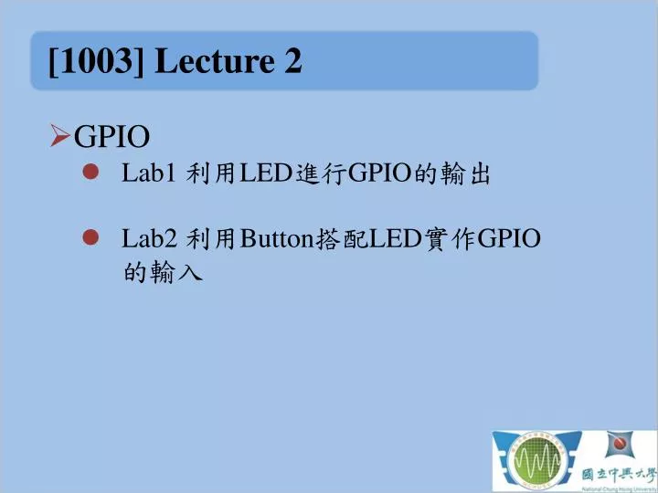
[1003]Lecture 2 • GPIO • Lab1 利用LED進行GPIO的輸出 • Lab2 利用Button搭配LED實作GPIO的輸入
[1003]Lecture 2 • Lab1 點亮D1 LED
[1003]Lecture 2 • 點亮D1LED
[1003]Lecture 2 P5.5 是位於Port5上的5號bit 點亮LED,是對外輸出訊號1 將GPIO 埠口設為輸出使用PxDIR暫存器 將GPIO 埠口的輸出設為1使用PxOUT
[1003]Lecture 2 • PxDIR、PxOUT的型式為一組8bits的位元組,形如:00000000 • 由右至左為Px.0~Px.7 • PxDIR中的bit 對應到各個埠口bit = 0 為INPUTbit = 1 為OUTPUT • PxOUT中的bit 對應到各埠口即為各埠口的輸出
[1003]Lecture 2 • 使用標準位元定義 • EX:BIT0 = 0x0001;BIT1 = 0x0002;BIT2 = 0x0004;BIT3 = 0x0008;BIT4 = 0x0010;BIT5 = 0x0020;BIT6 = 0x0040;BIT7 = 0x0080;
[1003]Lecture 2 • 使用標準位元定義 • EX:BIT5 = 0x0020; • 0000 0000 0010 0000 • 20hex = 32dec = 100000bin
[1003]Lecture 2 • 因此,點亮D1的敘述,即為 • P5DIR |= BIT5;//PORT5 的bit5設為1表示輸出訊號 • P5OUT|= BIT5;//PORT5 的bit5設為1表示輸出訊號為1
[1003]Lecture 2 • 接著,若要使LED自行閃爍,我們該怎麼做?
[1003]Lecture 2 • 接著,若要使LED自行閃爍,我們該怎麼做? • 使用XOR的邏輯 • XOR的運算子是 “ ^ ”
[1003]Lecture 2 • 閃爍LED的語法為:P5OUT^= BIT5 • 加入一些delay,使得結果更容易觀察__delay_cycles(100000);
[1003]Lecture 2 • 程式碼1點亮D1:#include “msp430x54x.h”void main(void){WDTCTL = WDTPW + WDTHOLD;P5DIR|= BIT5;P5OUT|= BIT5; • ※禁止複製貼上以免發生格式錯誤。
[1003]Lecture 2 • 程式碼2 閃爍D1:#include “msp430x54x.h”void main(void){WDTCTL = WDTPW + WDTHOLD;P5DIR|= BIT5;P5OUT^= BIT5;__delay_cycles(100000); • ※禁止複製貼上以免發生格式錯誤。
[1003]Lecture 2 • 練習:加入D2 LED。撰寫一個程式,使得D2 和D1能夠交替閃爍。 • 加分題:加入D3 LED。撰寫一個程式,使得D3能夠跟著D2閃爍。
[1003]Lecture 2 • Lab2 GPIO 輸入
[1003]Lecture 2 • 線路圖
[1003]Lecture 2 • 線路圖
[1003]Lecture 2 • GPIO 作為輸入時用到的暫存器 • PxDIRGPIO 介面方向;0為輸入,1為輸出。 • PxRENGPIOResistor Enable;是否使用上拉/下拉電阻。bit = 0 為不用;bit = 1 為使用。 • PxOUT在使用GPIO 作為輸入且Resistor enabled的情況下,PxOUT提供了選擇上拉/下拉電阻的功能。bit = 0 為下拉電阻bit = 1 為上拉電阻
[1003]Lecture 2 • 以第一個按鍵為例P2.0 • GPIO作為輸入所以Direction 設為0P2DIR &= ~BIT0; • 接著啟用上拉/下拉電阻P2REN|=BIT0; • 由電路圖我們知道,button按下為0電位(GND),放開為1電位,故我們上拉電阻。P2DIR|=BIT0;
[1003]Lecture 2 • 我們將按鍵輸入的功能加入LED發光的程式 • 利用輪詢的方式,使得按鍵壓下是D2,放開是D1
[1003]Lecture 2 • 程式碼:#include “msp430x54x.h”void main(void){WDTCTL = WDTPW + WDTHOLD;P2DIR&=~BIT0;P2REN|=BIT0;P2OUT|=BIT0;P5DIR|= BIT4+BIT5;while(1){ if(BIT0&P2IN) P5OUT = BIT5; else P5OUT=BIT4;}}
[1003]Lecture 2 • 練習:加入Key2,分別以Key1 控制LEDD1、Key2 控制LEDD2。 • 壓一下開始閃爍,再壓一下停止。
[1003]Lecture 2 • 完成後,找到專案裡面的source file,以附檔形式寄到 kchu@ares.ee.nchu.edu.tw,並在郵件中註明姓名、系級與學號。