Download
1 / 36
360 likes | 578 Views
ROUTING BASICS, RIP. Iskra Djonova-Popova. Why are Routers Necessary?. A. B. One of the key components of the technical infrastructure of the network Connect networks Provide the best path from the source to destination. R1. R2. R3. R4. R5. C. Internet. R2. A. R1. B.

E N D
ROUTING BASICS, RIP Iskra Djonova-Popova
Why are Routers Necessary? A B • One of the key components of the technical infrastructure of the network • Connect networks • Provide the best path from the source to destination R1 R2 R3 R4 R5 C
Internet R2 A R1 B Sending Packets through the Network • Sending packets on the same subnet • Default router • Using redirects • Discovering the local router
1 4 3 2 The Internal Elements of a Router Routing table Interfaces Destination Next hop Interface . . . . . . 1 . . . . . . 2 Routing Engine
Schematic View of a Router Incoming packets Outgoing packets Processing
The Routing Table • The crucial element of the router • defines the topology of the network • must be consistent with other router’s tables • Static and dynamic routing tables • static - when constructed by network administrator • dynamic - when constructed by routing protocols
Static Routes • Advantages • predictability • no overhead • simplicity • Disadvantages • lack of scalability • can not adapt to a failure in a network
172.16.5.0/24 172.16.3.0/24 172.16.5.1 172.16.3.1 R2 172.16.3.2 R3 172.16.4.1 172.16.2.0/24 172.16.2.1 172.16.4.0/24 R1 172.16.1.1 172.16.1.0/24 Example: hostname Router1 interface e0 IP 172.16.1.1 255.255.255.0 interface e1 IP 172.16.2.1 255.255.255.0 172.16.1.2 IP route 172.16.3.0 255.25.255.0 172.16.1.2 IP route 172.16.5.0 255.25.255.0 172.16.1.2 IP route 172.16.4.0 255.25.255.0 172.16.1.2
Dynamic Routes • Advantages • adapt to a failure in a network • work in large networks • Disadvantages • increase in complexity • overhead on the lines and routers
Hybrid Routing Schemes • Some parts use static and some parts dynamic routing • static routing on the access network • dynamic routing on the core and distribution network Core R1 R2 R3 Distribution R5 R6 R4 Access
Classification of the Routing Protocols • Where the protocol is used • Interior protocols (IGP) • Exterior protocols (EGP) • Kind of information that is carried and the way the routing table are calculated • Distance-vector protocols • Link-state protocols
IGP Vs EGP • Interior Gateway Protocols • within a single autonomous system • single network administration • unique routing policy • make best use of network resources • Exterior Gateway Protocols • among different autonomous systems • independent administrative entities • communication between independent network infrastructures
Distance-Vector Vs Link-State • Link-state protocols • Each router sends information about • links to which it is attached • state of these links • it is flooded throughout the network • every router calculates its routing table • Distance-vector protocols • Each router periodically sends to his neighbors • how far is the destination • the next hop to get there • Install routes directly in tables
The Role of IGPs • Maintain a coherent picture of the network topology and address domain in the router • Distribute this information to the other routers • Maintain consistent routing tables, such that the path to every destination is “optimal” • Converge quickly when there are changes in the network
R1 R4 5 R7 5 40 R6 B 5 10 6 R2 15 A 10 20 R8 10 4 5 10 R3 R5 Example: Choosing an Optimal Path
The Link Metric • Possible metrics • hop count • inverse of the link bandwidth • delay • dynamically calculated • administratively assigned • combination • Traffic should be monitored and metrics adjusted
Bandw. 256K Metric 14 1024K B 1024K 256K A 2 2 10 1 2048K 1 2048K 3 3 3 3 3 768K 768K 768K 768K 768K Bandw. 768K Metric 17 Example for Bad Metrics
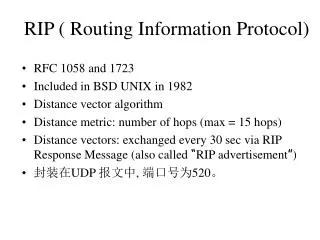
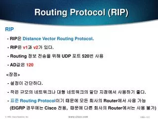
RIP - Routing Information Protocol • IGP, distance-vector protocol • First used in XNS (Xerox Network Systems) • Designed as a component of the networking code for the BSD release of UNIX • incorporated in program “routed” (rote management daemon) • First documented in rfc 1058
RIP - Characteristics • Packets are sent every 30 seconds or faster when necessary • Route is considered down if not refreshed within 180 sec. (distance set to infinity) • Two kinds of messages • request • response
RIP - Characteristics • The metric is a hop-count • The value of 1 to 15 is used (16 denotes infinity) • Bellman-Ford algorithm is used to find the shortest paths • Doesn't support classless routing • Used only in IP networks • at first the intention was to be used in variety of networks
Dest. Link Hop A local 0 B 1 1 E 2 1 Dest. Link Hop B local 0 A 1 1 C 4 1 E 3 1 Example: Dest. Link Hop C local 0 B 4 1 D 5 1 F 6 1 A Dest. Link Hop D local 0 C 5 1 G 7 1 B 1 C 4 D 5 2 3 6 7 E F E Dest. Link Hop E local 0 A 2 1 B 3 1 Dest. Link Hop G local 0 D 7 1 F 8 1 Dest. Link Hop F local 0 C 6 1 G 8 1 8 G
A B 1 Routing table for node A C 4 D 5 2 3 6 After four iterations 7 E F 8 After three iterations After two iterations G Dest. Link Hop A local 0 B 1 1 C 1 2 D 1 3 E 2 1 F 1 3 G 1 4 Dest. Link Hop A local 0 B 1 1 C 1 2 D 1 3 E 2 1 F 1 3 Dest. Link Hop A local 0 B 1 1 C 1 2 E 2 1
A B 1 C 4 D 5 2 6 3 7 after the failure of link 1 before the failure of link 3 E F 8 Dest. Link Hop E local 0 A 2 1 B 3 1 C 3 2 D 3 3 F 3 3 G 3 4 G Dest. Link Hop A local 0 B - - C - - D - - E 2 1 F - - G - - Dest. Link Hop A local 0 B 2 2 C 2 3 D 2 4 E 2 1 F 2 4 G 2 5 In Case of a Link Failure Routing table of node A
Split-Horizon and Poison Reverse • Split-horizon • the information about destination routed on the link is omitted • Poison reverse • the corresponding distance is set to infinity if the destination is routed on the link
Triggered Updates • A timer is associated with each entry in the routing table • much longer than the period of transmission of information • Triggered updates • request nodes to send messages as soon as they notice a change in the routing table
Advantages and Disadvantages • Advantages • Simple to implement • Low requirement in processing and memory at the nodes • Suitable for small networks • Disadvantages • Slow convergence • Bouncing effect • Counting to infinity problem
RIP - Message Format 0 31 Command(1) Version (1) Must be zero(2) Address family identifier (2) Must be zero(2) IP address (4) Must be zero(4) Must be zero(4) Metric (4)
RIP - Limitations • Maximum hop count of 15 • restricts the use of RIP in larger networks, but prevents the count to infinity problem (endless loops) • Difference in links speed is not reflected in the hop-count metrics • congested links can be still included in the best path
RIP II - Why Was Developed? • Many superior IGP exists (RIP is often referred as Rest In Peace) • There are still many implementations of RIP • Given that RIP will still be used, it deserves improvements • RIP II is documented in RFC-1287, RFC-1388 and RFC-2453
RIP II - Message Format Command (1) Version (1) Routing domain(2) Address family identifier (2) Route Tag(2) IP address(4) Subnet Mask(4) Next Hop(4) Metric(4)
RIP II - The Added Fields • Routing domain • used together with the next hop field to allow multiple autonomous systems to share a single wire • Route tag • to flag external routes (for use by EGP and BGP) • Subnet mask • to support subnets • Metric
RIP II - Improvements • Authentication • uses a simple password procedure • Routing per subnet • Support of multiple metrics • hop count, throughput, measured as 10logC • Routing domains • Multicasting • Compatible with RIP
RIP is not alone!IGRP and EIGRP • Interior Gateway Protocol was developed in the mid1980s by Cisco Systems, Inc. • Designed to overcome the limitations of RIP • Initially worked in IP environment, but latter ported to OSI CLNP networks
IGRP - Main Characteristics • Distance vector protocol • Uses a combination of metrics • internetwork, delay, bandwidth, reliability and load • the weighting factors are set either by administrators or default values are used
IGRP - Additional flexibility • Wide metric ranges • allow satisfactory metric setting in internetworks with widely varying performance characteristics • Permits multipath routing • dual equal-bandwidth lines may run a single stream of traffic in round-robin fashion
EIGRP • Enhanced version of IGRP • Improvements • convergence properties • The Distributed Update Algorithm (DUAL) is used to obtain loop-freedom throughout a route computation • operational efficiency • Provides compatibility with IGRP