Download
1 / 58
600 likes | 812 Views
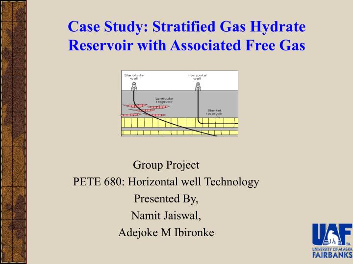
Case Study: Stratified Gas Hydrate Reservoir with Associated Free Gas. Group Project PETE 680: Horizontal well Technology Presented By, Namit Jaiswal, Adejoke M Ibironke. Objective. Gas Hydrates Overview of horizontal well and designer well Case description Results Conclusion

E N D
Case Study: Stratified Gas Hydrate Reservoir with Associated Free Gas Group Project PETE 680: Horizontal well Technology Presented By, Namit Jaiswal, Adejoke M Ibironke
Objective • Gas Hydrates • Overview of horizontal well and designer well • Case description • Results • Conclusion • Recommendation
Alaska Methane Hydrate Estimated Resource EILEEN TREND MPU 100% FREE GAS? 44 TCF KRU 39% DIU PBU 26% GAS HYDRATE & FREE GAS 60 TCF? GAS HYDRATE TARN TREND (After Collett, 1993)
GAS HYDRATES – AN OVERVIEW • Crystalline structures of ice that form cages around guest molecules • Guests are gas molecules (methane, ethane, CO2, N2…) • No chemical bond between guest and host lattice • Physically stable with only partial occupancy • Different structures sI, sII, sH, sT, …? • Large amounts of gas molecules are entrapped within these cages • Up to 180 volumes of gas (scf) per volume of hydrate • Gas molecules can penetrate through the hydrate zone to form new gas hydrates at boundary • Formation and growth occurs only under certain pressure and temperature conditions • Hydrate formation conditions are high pressure and low temperature
Gas Hydrate Production Methods Depressurization Thermal Injection Inhibitor Injection Methanol Hot Brine or Gas Gas Out Gas Out Gas Out Imperm. Rock Imperm. Rock Imperm. Rock Gas Hydrate Gas Hydrate Gas Hydrate Hydrate Dissociated Free-Gas Reservoir Dissociated Hydrate Dissociated Hydrate Impermeable Rock Impermeable Rock After Collett, 2000
Boundary Condition Gas zone Hydrate zone Pin t Peq Po Pwf Radial distance
Algorithm for Performance of a Hydrate Reservoir Evaluation • Assume an average pressure pavg, and calculate gas compressibility cg using • Using the value of cg , calculate total compressibility and hydraulic diffusivity constant from the known reservoir parameters. • For a desired gas withdrawal rate, solve eqn Above equation has on both sides; it requires a numerical scheme to solve. As a special case, when there is no gas flow from the undissociated hydrate zone, so above equation is simplified to
Above equation has on both sides; it requires a numerical scheme to solve. As a special case, when there is no gas flow from the undissociated hydrate zone, so above equation is simplified to • Using the value of , solve below equation (1) and (2 • Using the value R*, Po and solve eq 3. and 4.
and for the un-dissociated region is to obtained pressure profiles as a function of radial distance from the wellbore. • From the pressure values obtained in step 5. find pwf and calculate a new average pressure using • Using the new value of pavg, calculate new values of cg, ct and . Compare the new value of with that calculated in step 2. If the new value is within 10% of the old value, use the pressure profile generated in step 5. If not, go to step 3 and repeat Steps 4-8 till the consecutive values of agree.
Parameter Effects • Skin Factor • Payzone thickness • Anisotropy
Productivity by Well Testing • To obtain reservoir properties • To find total producing length • To estimate mechanical skin factor
Gas Reservoir • Low Permeability
High Permeability hydrate
Water and Gas Coning Vertical well Horizontal well
6 x 50’ 2’ Kh=15 md Case Description Highly Stratified Gas Hydrate Reservoir 0.35’
Temperature for free gas zone is constant. Average viscosity is used for calculation. Individual well bore pressure are assumed taken from literature. Pressure drop across tubing is negligible. ASSUMPTIONS FOR VERTICAL WELL RESERVOIR
Productivity for vertical gas well is calculated by using following equation: Where, q = gas flow rate, Mscfd k= permeability, md h = Thickness, ft Pe =Pressure at external radius, re, Psia Pwf = well bore flowing pressure, Psia Z= average compressibility factor T = Reservoir temperature, R re = drainage radius, ft
Vertical Fractured Wells • Any technique that helps to create fissures and openings in the reservoir rock of an oil and (or) gas formation, and help increase the flow of oil and (or) gas.
Techniques • Fracturing can either be • Natural - created by faults in the formation) • Artificial -This can be • Pneumatic - by the flow of high pressure compression of air. • Hydraulic - pumping of fluid under high pressure.
Application • Increase the flow rate of gas from low permeability reservoirs. • Increase the flow rate of gas from wells that have been damaged. • Connect natural fractures or cleats in a formation to the wellbore. • Decrease pressure drop around well to minimize sand production. • Decrease pressure drop around well to minimize problems with asphaltene or paraffin deposition. • Increase the area of drainage. • Connects the full vertical extent of a reservoir to a slanted or horizontal well.
Candidate Selection • Must have a need to increase the productivity index. • A thick pay zone. • Medium to high pressure. • In-situ stress barriers to minimize vertical height growth. • It will either be a low permeability zone or a zone that has been damaged (high skin factor). • Must have a substantial volume of gas in place.
A fractured vertical well behaves much like a horizontal well. • Advantages of Fractured Vertical Wells • Can be used in thick formations • Not affected by low vertical permeability • Disadvantages of Fractured Vertical Wells • No control over the fracture orientation • Possibility of uncontained fracture growth resulting in excessive gas or water influx. • TYPES OF FRACTURES • INFINITE-CONDUCTIVITY FRACTURES • UNIFORM FLUX FRACTURES • FINITE-CONDUCTIVITY FRACTURES
Assumptions • Drainage volume is box shaped • The well fully penetrates the formation • There is no restricted entry to flow • The production is predominantly stabilized flow for all layers • The effect of non-Darcy flow is ignored • The rock property in each layer is the same
Conclusion • Vertical fracture well productivity decreases with pay thickness • Fracture can only be beneficial when permeability is relatively low • For the gas hydrate reservoir, it is expedient to perforate in the free gas zone
α SLANT WELL
α Definition • A directionally drilled well, that is inclined at an angle α to the vertical. • α is usually between 30˚-75˚ to be effective
To reduce the cost of drilling several wells from a single platform To allow extraction of oil/gas from areas unreachable conventionally In reservoir with down-dip For formation with low permeability to gas The Great Lakes, along the shores of Lake Michigan and Huron In the Coalbed Methane field of Valencia Canyon in Northern San Juan basin of Colorado. In the Greater Green River Basin of Colorado. Reason for use & Areas of Practical Application
The slant well is highly dependent on the vertical permeability When the kv is low, then productivity will be low Gas migrates vertically upward and because the kv is very low the productivity turned out low The result shows that the slant well has a higher productivity than the vertical well Conclusion
A steady state equation for gas flow in a Horizontal section • Where, • q = gas flow rate, Mscf/day kh= permeability, md • h = Thickness, ft Pe =Pressure at external radius, re, Psia • Pwf = wellbore flowing pressure, Psia • Z= average compressibility factor • T = Reservoir temperature, R • re = drainage radius, ft r'w =effective wellbore radius, ft • = SQRT (kh/kv) Sm = mechanical skin factor
Negligible pressure drop. Permeability of each zone is same No production from vertical sections. Open hole completion to increase hydrate production in long run. Assumptions
Initialization For stratified well the partial differential equation, Pj denoting the pressure in the jth layer, Cases : Shell Barrier Communication
Multilateral well in hydrate reservoir with no communication
A Steady state equation for Multilateral Well Where, F=4,2,1.86 and 1.78 for n=1,2,3,4. m =number of levels. For this case, m=6 and n=1.