Download
1 / 30
300 likes | 443 Views
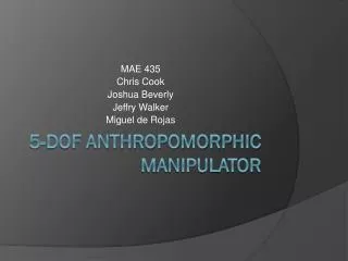
MAE 435 Chris Cook Jeffry Walker Joshua Beverly Miguel de Rojas. 5-DOF Anthropomorphic Manipulator. Types of Manipulators. Cartesian Gantry Cylindrical Spherical SCARA Anthropomorphic – Make of 59% in use worldwide as of 2005 IFR report. Types of Manipulators. Welding Manipulator.

E N D
MAE 435 Chris Cook Jeffry Walker Joshua Beverly Miguel de Rojas 5-DOF Anthropomorphic Manipulator
Types of Manipulators • Cartesian • Gantry • Cylindrical • Spherical • SCARA • Anthropomorphic – Make of 59% in use worldwide as of 2005 IFR report
Project Goals • 5cm x 5cm x 5cm cube • Placed within 6 in radial position • Repeated TBD number of times
Preliminary Calculations JointMass=.939; %mass of joint (kg) ShaftMass=.113; %mass of shaft (kg) ShaftLength=.2032; %length of shaft (m) MotorOutput=.4862; %N-m output torque peak effective GearRation=132; %ratio of planetary gearbox LoadLifted=.34; %minimum mass to be picked up (kg) g=9.81; %gravity %effective forces jf=JointMass*g; sf=ShaftMass*g; lf=LoadLifted*g; L=ShaftLength; %Joint Torques J1torque=lf*3*L+jf*L*(3+2+1)+sf*L*(2.5+1.5+.5); J2torque=lf*2*L+jf*L*(2+1)+sf*L*(1.5+.5); J3torque=lf*L+jf*L+sf*L*.5;
Midterm Status Update • Machining and assembly complete unless modifications become necessary • Inventor solid model complete unless modifications become necessary • Wiring is complete pending testing • Computer code for the microcontroller is in development • Dynamics/Kinematics in development
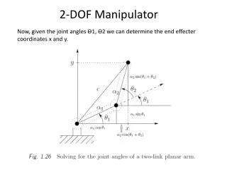
Forward Kinematics • Denavit-Hartenberg Parameters • 3 fixed-link parameters αi and ai: describe the Link i • di and θi : describe the Link’s connection
Inverse Kinematics • Goal: determine all the joint variables for a specific end-effector position and orientation • Feed this information to the controls
Inverse Kinematics • Determine the inverse kinematics starting from this equation
Closed-Loop Feedback Control • PID Controller • (Proportional Integral Derivative)
5-DOF Manipulator • 5-DOF Manipulator in Action • 2:08
References • 1. Siciliano, B., et al., Robotics Modeling, Planning and Control. Advanced Textbooks in Control and Signal Processing2009: Springer. • 2. Lee, C.S.G., Robot Arm Kinematics, Dynamics, and Control. Computer, 1982. 15(12): p. 62-80. • 3. MathWorks MATLAB • 4. Autodesk Inventor • 5. Microsoft Office Suite