Download
1 / 44
1.34k likes | 3.14k Views
3D VIEWING. 3D Viewing-contents. Viewing pipeline Viewing coordinates Projections View volumes and general projection transformations clipping. 3D Viewing. World coordinate system (where the objects are modeled and defined)

E N D
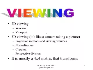
3D Viewing-contents • Viewing pipeline • Viewing coordinates • Projections • View volumes and general projection transformations • clipping
3D Viewing • World coordinate system(where the objects are modeled and defined) • Viewing coordinate system(viewing objects with respect to another user defined coordinate system) • Scene coordinate system(a viewing coordinate system chosen to be at the centre of a scene) • Object coordinate system(a coordinate system specific to an object.)
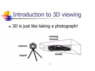
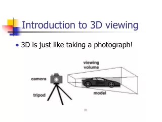
3D viewing • Simple camera analogy is adopted
3D viewing • Defining the viewing coordinate system and specifying the view plane
3D viewing steps to establish a Viewing coordinate system or view reference coordinate system and the view plane First pick up a world coordinate position called the view reference point. This is the origin of the VC system Pick up the +ve direction for the Zv axis and the orientation of the view plane by specifying the view plane normal vector ‘N’. Choose a world coordinate position and this point establishes the direction for N relative to either the world or VC origin. The view plane normal vector is the directed line segment.
3D viewing • steps to establish a Viewing coordinate system or view reference coordinate system and the view plane Some packages allow us to choose a look at point relative to the view reference point. Or set up a Left handed viewing system and take the N and the +ve Zv axis from the viewing origin to the look- at point.
3D viewing • steps to establish a Viewing coordinate system or view reference coordinate system and the view plane We now choose the view up vector V. It can be specified as a twist angle about Zv axis. Using N,V U can be specified. Generally graphics packages allow users to choose a position of the view plane along the Zv axis by specifying the view plane distance from the viewing origin. The view plane is always parallel to the XvYv plane.
3D viewing To obtain a series of views of a scene we can keep the view reference point fixed and change the direction of N or we can fix N direction and move the view reference point around the scene.
3D viewing Transformation from world to viewing coordinate system Mwc,vc=RzRyRx.T (b) Translate Viewing Origin to World Origin (a) Invert Viewing z Axis (c) Rotate About World x Axis to Bring Viewing z Axis into the xz Plane of the World System (d) Rotate About the World y Axis to Align the Two z Axes (e) Rotate About the World z Axis to Align the Two Viewing Systems
What Are Projections? Picture Plane Objects in World Space Our 3-D scenes are all specified in 3-D world coordinates To display these we need to generate a 2-D image - project objects onto a picture plane
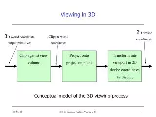
Converting From 3-D To 2-D • Projection is just one part of the process of converting from 3-D world coordinates to a 2-D image 3-D world coordinate output primitives Clip against view volume Project onto projection plane Transform to 2-D device coordinates 2-D device coordinates
Types Of Projections • There are two broad classes of projection: Parallel: Typically used for architectural and engineering drawings Perspective: Realistic looking and used in computer graphics Parallel Projection Perspective Projection
Types Of Projections • There are two broad classes of projection: • Parallel: preserves relative proportions of objects accurate views of various sides of an object can be obtained does not give realistic representations of the appearance of a 3D objective. • Perspective: produce realistic views but does not preserve relative proportions projections of distant objects are smaller than the projections of objects of the same size that are closer to the projection plane.
Parallel Projections • Some examples of parallel projections Orthographic oblique Orthographic Projection(axonometric)
Parallel Projections • Some examples of parallel projections The projection plane is aligned so that it intersects each coordinate axes in which the object is defined (principal axes) at the same distance from the origin. All the principal axes are foreshortened equally. Isometric projection for a cube
Parallel Projections Transformation equations for an orthographic parallel projections is simple Any point (x,y,z) in viewing coordinates is transformed to projection coordinates as Xp=X Yp=Y
Parallel Projections Oblique projections Transformation equations for oblique projections is as below.
Parallel Projections Oblique projections Transformation equations for oblique projections is as below. An orthographic projection is obtained when L1=0. In fact the effect of the projection matrix is to shear planes of constant Z and project them on to the view plane. • Two common oblique parallel projections: • Cavalier and Cabinet
Parallel Projections Oblique projections • 2 common oblique parallel projections: Cavalier projection Cabinet projection They are more realistic than cavaliar Lines perpendicular to the viewing surface are projected at one-half their length. All lines perpendicular to the projection plane are projected with no change in length.
Perspective Projections • Perspective • visual effect is similar to human visual system... • has 'perspective foreshortening‘ • size of object varies inversely with distance from the center of projection. • angles only remain intact for faces parallel to projection plane.
Perspective Projections Where u varies from o to 1
Perspective Projections If the PRP is selected at the viewing cooridinate origin then Zprp=0 The projection coordinates become Xp=X(Zvp/Z) Yp=Y(Zvp/Z) If the view plane is the UV plane itself then Zvp=0. The projection coordinates become Xp=X(Zprp/(Zprp-Z))=X(1/(1-Z/Zprp)) Yp=Y(Zprp/(Zprp-Z))=Y(1/(1-Z/Zprp))
Perspective Projections • There are a number of different kinds of perspective views • The most common are one-point and two point perspectives Coordinate description Two-point perspective projection One-point perspective projection
Perspective Projections Parallel lines that are parallel to the view plane are projected as parallel lines. The point at which a set of projected parallel lines appear to converge is called a vanishing point. If a set of lines are parallel to one of the three principle axes, the vanishing point is called an principal vanishing point. There are at most 3 such points, corresponding to the number of axes cut by the projection plane.
View volume Perspective projection Parallel projection The size of the view volume depends on the size of the window but the shape depends on the type of projection to be used. Both near and far planes must be on the same side of the reference point.
View volume Often the view plane is positioned at the view reference point or on the front clipping plane while generating parallel projection. Perspective effects depend on the positioning of the projection reference point relative to the view plane
View volume - PHIGS View Plane Front Clipping Plane Back Clipping Plane Direction of Propagation Back Clipping Plane Back Clipping Plane View Plane View Plane Front Clipping Plane Front Clipping Plane Direction of Propagation
View volume In an animation sequence, we can place the projection reference point at the viewing coordinate origin and put the view plane in front of the scene. We set the field of view by adjusting the size of the window relative to the distance of the view plane from the PRP. We move through the scene by moving the viewing reference frame and the PRP will move with the view reference point.
General parallel projection transformation • Parallel Far Plane View Volume Direction of Projection Near Plane Window (a) Original Orientation Far Plane View Volume Direction of Projection Near Plane Window (b) After Shearing
General parallel projection transformation • Parallel Let Vp=(a,b,c) be the projection vector in viewing coordinates. The shear transformation can be expressed as V’p=Mparallel.Vp Where Mparallel is For an orthographic parallel projection Mparallel becomes the identity matrix since a1=b1=0 Shearing
Regularization of Clipping (View) Volume (Cont’) General perspective projection transformation • Perspective Far Far View Volume View Volume Near Near Window Window Center of Projection Center of Projection (a) Original Orientation (b) After Transformation Shearing
General perspective projection transformation • Perspective • Steps • Shear the view volume so that the centerline of the frustum is perpendicular to the view plane • Scale the view volume with a scaling factor that depends on 1/z. Mperspective=Mscale.Mshear A shear operation is to align a general perspective view volume with the projection window. The transformation involves a combination of z-axis shear and a translation.
Clipping View volume clipping boundaries are planes whose orientations depend on the type of projection, the projection window and the position of the projection reference point The process of finding the intersection of a line with one of the view volume boundaries is simplified if we convert the view volume before clipping to a rectangular parallelepiped. i.e we first perform the projection transformation which converts coordinate values in the view volume to orthographic parallel coordinates. Oblique projection view volumes are converted to a rectangular parallelepiped by the shearing operation and perspective view volumes are converted with a combination of shear and scale transformations.
Clipping-normalized view volumes The normalized view volume is a region defined by the planes X=0, x=1, y=0, y=1, z=0, z=1
Clipping-normalized view volumes • There are several advantages to clipping against the unit cube • The normalized view volume provides a standard shape for representing any sized view volume. • Clipping procedures are simplified and standardized with unit clipping planes or the viewport planes. • Depth cueing and visible-surface determination are simplified, since Z-axis always points towards the viewer. Unit cube Mapping positions within a rectangular view volume to a three-dimensional rectangular viewport is accomplished with a combination of scaling and translation. 3D viewport
Clipping-normalized view volumes Mapping positions within a rectangular view volume to a three-dimensional rectangular viewport is accomplished with a combination of scaling and translation. Dx 0 0 Kx 0 Dy 0 Ky 0 0 Dz Kz 0 0 0 1 Unit cube 3D viewport Where Dx=(xvmax-xvmin)/(xwmax-xwmin) and Kx= xvmin- xwmin Dx Dy= (yvmax-yvmin)/(ywmax-ywmin) and Ky= yvmin - ywmin Dy Dz= (zvmax-zvmin)/(zwmax-zwmin) and Kz= zvmin- zwmin Dz
Viewport clipping For a line endpoint at position (x,y,z) we assign the bit positions in the region code from right to left as Bit 1 = 1 if x< xvmin (left) Bit 1 = 1 if x< xvmax (right) Bit 1 = 1 if y< yvmin (below) Bit 1 = 1 if y< yvmax (above) Bit 1 = 1 if z< zvmin (front) Bit 1 = 1 if z< zvmax (back)
Viewport clipping For a line segment with endpoints P1(x1,y1,z1) and P2(x2,y2,z2) the parametric equations can be X=x1+(x2-x1)u Y=y1+(y2-y1)u Z=z1+(z2-z1)u
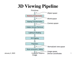
Hardware implementations Transformation Operations WORLD-COORDINATE Object descriptions Clipping Operations Conversion to Device Coordinates