Download
1 / 23
280 likes | 640 Views
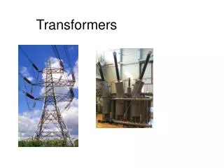
Transformers. Purpose: to change alternating (AC) voltage to a bigger (or smaller) value. changing flux in secondary induces emf. input AC voltage in the primary produces a flux. Principle of Transformer Action. Principle of Transformer Action. Principal of Transformer Action

E N D
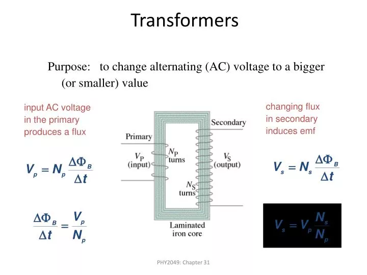
Transformers Purpose: to change alternating (AC) voltage to a bigger (or smaller) value changing flux in secondary induces emf input AC voltage in the primary produces a flux PHY2049: Chapter 31
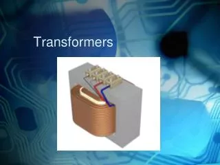
Principle of Transformer Action • Principal of Transformer Action • Principle of electromagnetic induction. • Ideal tωo ωinding transformer • ωinding resistances are negligible • Fluxes confined to magnetic core • Core lose negligible • Core has constant permeability • V1 I1 MMF = N1Ie • Core flux φ folloωs, Ievery closely. • Ie & φ sinusoidal • φ =φmax sinωt
Transformers • Nothing comes for free, however! • Increase in voltage comes at the cost of current. • Output power cannot exceed input power! • power in = power out
Transformers: Sample Problem • A transformer has 330 primary turns and 1240 secondary turns. The input voltage is 120 V and the output current is 15.0 A. What is the output voltage and input current? step-up transformer
Equivalent circuit referred to the LT side of a 250/2500 single phase transformer is shown in fig. The load impedance connected to HT is 380+j230Ω. For a primary voltage of 250V, compute • the secondary terminal voltage • primary current and power factor • Power output and efficiency
Equivalent circuit referred to the LT side of a 250/2500 single phase transformer is shown in fig. The load impedance connected to HT is 380+j230Ω. For a primary voltage of 250V, compute • the secondary terminal voltage • primary current and power factor • Power output and efficiency • Z'L = (380+j230) (N1 / N2)2 • = (380+j230) (250/2500)2 • = 3.8+j2.3 • Total impedance in the primary Secondary terminal voltage = I2ZL
Im= V1/jXm = 250∟0°/250∟90° =1∟-90° =0-j1 I'e = Ic + Im = 0.5+ (0-j1) = 0.5-j1 I'1= I'1 +I‘e = 40- j30+0.5- j1= 51∟-37.4° b) Primary current I1 = 51A Primary p.f = cosθ1 = cos37.4° = 0.794 lagging (c) Load p.f • cosθ2 = 380°/ (3802+2302 )= 0.855 • Power Output = V2I2cosθ2 = 2220*5*0.855 = 9500 Watts • Power Output = I'12RL = 502*3.8 = 9500 Watt • Core Loss ,PC= v12 / RC = Ic2 RC = 0.52*0.2 =500 Watts • Power Input = V1I1cosθ1 = 250*51*0.794 = 10123.5