Download
1 / 19
190 likes | 312 Views
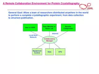
A Remote FPGA Laboratory Environment. By David Hehir Supervisor: Dr. Fearghal Morgan Co-Supervisor: Prof. Gearóid Ó Laighn Final Year Project Presentation. Contents. Initial Aims Introduction Hardware VHDL Graphical User Interface Future Work Summary. Initial Aims.

E N D
A Remote FPGA Laboratory Environment By David Hehir Supervisor: Dr. Fearghal Morgan Co-Supervisor: Prof. Gearóid Ó Laighn Final Year Project Presentation
Contents • Initial Aims • Introduction • Hardware • VHDL • Graphical User Interface • Future Work • Summary
Initial Aims • Enable use of board LEDs and Displays through VHDL • Enable these switches/buttons “Virtually” • Establish a communications link for the Lab • Create a GUI to implement Implement the Virtual design • Develop a real-time Virtual Laboratory for students
Introduction • Local PC/User PC will be given details of Lab Computer – IP/Password • User will download the template VHDL file containing the necessary files. Can now edit/compile locally on Local PC. • By logging on through a Virtual Networking Client (VNC) the user will have control • The webcam will relay the image of the FPGA back to the user.
Enabling Board LEDs/Switches • The following graphic shows how the LEDs and Seven-Segment Displays on the Spartan 3 Starter Board are assigned in the physical scenario. • The four spring-loaded push buttons will be connected to the LEDs shown • The switches will be loading the seven-segment displays with a HEX value (0 to F) • Digits are assigned the names digit3, digit2, digit1, digit0 in that respective order
Webcam • Logitech Quickcam Plug-and-Play – chosen for ease of setup • Live Video: Capture video at a size • Manual Focus: Adjust for the sharpest picture.
User Code – Skeleton.vhd • The skeleton is the main user design part of the template. It connects the buttons and switches to the Digit Displays and the LEDs • All the other functions such as the UART and display Controller will stay the same(although will be open to editing also) • The user can open the Skeleton.vhd file. • From the ‘skeleton’ they can also change with LEDs and which Digit displays they would like to use. • The user can now add their own code to, e.g. create a binary counter, change the sequence in which the LEDs light, add their own design essentially.
Generate/Upload Bitstream File • User will compile and generate bitstream(.bit) file • Upload code to Host • Send to board (iMPACT) • Code will be viewable running
Graphical User Interface The Original AppliedVHDL GUI was designed by previous students including Martin O’Halloran. The functionality of it includes: • CSR Read/Write • RAM Read/Write • Digital Image Processing
Graphical User Interface Original GUI Modified GUI
Graphical User Interface The additional controls were added by Visual Basic: • The Virtual Controls must be enabled first • LEDs have GUI buttons assigned to them • Data can be displayed by inputting HEX or Binary values and submitting to board • Controls can then again be disabled
UltraVNC • Modified and updated version of VNC • Freeware • Open-Source • File transfer supported • Chat functionality • Admin security • Viewer/Server • Easy to use
Laboratory Interface • The laboratory screen will contain: • AppliedVHDL GUI • iMPACT • Webcam view
Future Work • Considering what additional GUI controls may be useful to a user. • Considering what additional FPGA elements may be useful in a user library. • Extending the system for use with the NEXYS Spartan-3 development system, its GUI and USB interface. • Developing a new memory controller within the appliedVHDL system to allow operation on the NEXYS system. • Editing source of UltraVNC to further project