Download
1 / 20
200 likes | 227 Views
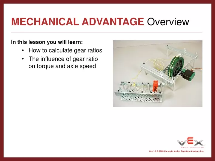
MECHANICAL ADVANTAGE Overview. In this lesson you will learn: How to calculate gear ratios The influence of gear ratio on torque and axle speed. Background Calculating Gear Ratio.

E N D
MECHANICAL ADVANTAGEOverview • In this lesson you will learn: • How to calculate gear ratios • The influence of gear ratio on torque and axle speed
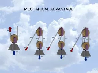
BackgroundCalculating Gear Ratio • When only two gears are involved, the gear ratio is simply the ratio of the number of teeth on the driven gear to the number of teeth on the driving gear. • When there are multiple gears on a single axle, the overall gear ratio can be calculated by multiplying the individual gear ratios as if they were fractions.
Background Compound Gear Ratios 5:1 • The simple gear ratios in the picture to the right are 3:1 (36 teeth on driven gear; 12 teeth on driving gear) and 5:1 (60 teeth on driven gear; 12 teeth on driving gear) • In order to find the compound gear ratio, you need to multiply the gear ratios which make up the compound gear ratio by each other. • So the compound gear ratio is 3/1 x 5/1, which equals 15/1, or 15:1 • You can calculate compound gear ratios made up of more than two simple gear ratios by the same method. If there were 3 simple gear ratios, and the gear ratios were 3/1, 5/1 and 5/1, the compound gear ratio would be 3/1 x 5/1 x 5/1 which equals 75/1, or 75:1 3:1
Background Torque • Torque can be used to describe the rotational strength of a motor. • The torque generated by an axle is linearly related to the gear ratio. Therefore, increasing the gear ratio can improve a hoist’s ability to lift heavy objects. • See torque helper page and gear ratios and torque helper page for more information.
Lesson Materials Needed • Constructed Gear Box and Lifting Crate—Please note: we used a crate and rolls of pennies because we thought they're easily available. Feel free to substitute whatever lifting apparatus and/or weights you prefer. An especially good solution is a strong spring scale (20 - 60 lb. maximum). By anchoring the spring scale, then tying it to the string, you do not need to use a crate or weights. • Rolls of pennies • Stopwatch • String • Radio Transmitter
Lesson Step 1 • Follow the instructions to build the lifting crate and the first stage of the gearbox
Lesson Step 2 • You may have to re-download the RobotC firmware if you have ever downloaded any programs or other firmware to the microcontroller. (If nothing has been downloaded to the microcontroller after downloading the ROBOTC firmware, you may skip • this step.) • • Connect the programming module to • both the PC and the microcontroller • • Make sure the microcontroller is • turned on • • Open ROBOTC. • • Select Robot/Download Firmware • • Select VEX VM 0724.hex/Open (or • later version of ROBOTC firmware).
Lesson Step 3 • Calculate RPM • Record the time it takes for the wheel to make ten full revolutions • Calculate the rotational speed in rev/s • Convert the value to rev/min (rpm)
Lesson Step 4 • Place 1 roll of pennies in the lifting crate and tie it to the spool on the motor’s axle.
Lesson Step 5 • Test the system to see if the gear box is capable of lifting the load.
Lesson Step 6 • Continue to add rolls of pennies to the crate until the gearbox can no longer raise the load. Record the maximum weight that the gearbox could lift.
Lesson Step 7 • Modify the gearbox so the wheel is on the second axle. • Determine the gear ratio between driven and driving axles.
Lesson Step 8 • Calculate the rpm and compare it to axle 1. • Use the gear ratio and the data from the first axle to calculate the maximum weight that the axle could lift if the spool were placed on it.
Lesson Step 9 • Tie the lifting crate to the spool and measure the maximum weight that the gearbox can lift using this axle. • How does this measured value compare to your theoretical value?
Lesson Step 10 • Modify the gearbox so the spooling wheel is on the third axle.
Lesson Step 11 • Predict, and then calculate, the rpm for this axle. • Predict the maximum weight that this axle can lift.
Lesson Step 12 • If an appropriate set of weights is available, test the theoretical value you just calculated.
Lesson Step 13 • Repeat the steps for the final axle • Predict and measure rpm • Predict maximum weight • If possible, measure maximum weight
Lesson Analysis • Graph your results: • RPM vs. Gear Ratio • Lifting Capability vs. Gear Ratio • Find the best-fit line • Find the slope of the best-fit line • Extension activity--discuss: What would happen to the gear ratio if the spooling wheel had a smaller diameter? Could you predict the amount a different-sized wheel would lift using gear ratios, the Lever Law, or both?