Download
1 / 28
400 likes | 1.17k Views
Homemade VHF and UHF Antennas. What criteria am I looking for in an antenna?. It is like looking for a car. How many people will it hold? What is the gas mileage? 2 wheel drive, 4 wheel drive, all wheel drive? Does it have enough power to tow my boat?.

E N D
What criteria am I looking for in an antenna? • It is like looking for a car. • How many people will it hold? • What is the gas mileage? • 2 wheel drive, 4 wheel drive, all wheel drive? • Does it have enough power to tow my boat?
What criteria am I looking for in an antenna? • Polarity • Gain • Size • Directionality • Portability • Multi band
Gain • What gain is • How it is expressed • How it is connected to an antenna
Gain (Horse Power + Drivetrain) • An antenna's power gain or simply gain is a key performance figure which combines the antenna's directivity and electrical efficiency. As a transmitting antenna, the gain describes how well the antenna converts input power into radio waves headed in a specified direction. As a receiving antenna, the gain describes how well the antenna converts radio waves arriving from a specified direction into electrical power. Due to reciprocity, the specified gain for any antenna applies identically whether it is used for transmitting or receiving.
Gain • Antenna gain can be specified in a few different ways, sometimes invoking confusion. Most often gain is expressed in decibels with the units denoted as dBi. However sometimes the gain is compared to the maximum gain of a lossless half-wave dipole antenna (1.64-2.2) in which case the units are written as dBd. • Gain is always a comparison to something else
Gain • For a given frequency the antenna's effective area is proportional to the power gain. An antenna's effective length is proportional to the square root of the antenna's gain for a particular frequency and radiation resistance. • In other words, the as length increases the gain increases exponentially.
Why do I care? • Gain is a major factor as to how well an antenna functions both in transmit and receive. • Power Gains • 3 db = X2 power • 6 db = X4 power • 10 db = X10 power • 20 db = X100 power • Power Loss • -3 db = ½ power • -6 db = ¼ power • -10 db = 1/10 power • -20 db = 1/100 power
Reading Materials • ARRL Antenna Source Book • QST Magazine • Internet • Most of the designs in this presentation were found online.
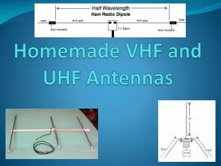
Basic antenna types • Dipole antenna, consists of 2 radiating elements apposed from each other, feed point is at the center of the 2 elements • Ground plane antenna, consists of one radiating element and a ground plane, feed point is at the connection of the ground plane and the radiating element • Yagi antenna, directional dipole, dB, how long do you want to make it? • 1/4 Wave length radiators 2.2 dBi, 0 dBd • 1/2 Wave length radiators 3.8 dBi, 1.6 dBd • 5/8 Wave length radiators 5.2 dBi, 3.0 dBd This reference material uses 2.2 dB as dipole gain
Collinear Antennas • A collinear antenna is 2 or 3 radiating elements stacked on top of each other separated by a phasing coil to increase gain • 5/8 Wave over 1/4 wave 5.4dBi, 3.2dBd • 5/8 Wave over 1/2 wave 5.6dBi, 3.4dBd • 5/8 Wave over 5/8 Wave over 1/4 wave 7.2dBi, 5.0dBd • 5/8 Wave over 5/8 Wave over 1/2 wave 7.6dBi, 5.4dBd
Construction tips • Soldering • Solder iron • Solder gun • Propane torch • Heat shrink • Encapsulating • Non encapsulating • PVC tubing • Loading effect • Ferrite chokes • Waterproofing
SWR • VSWR Voltage standing wave ratio, commonly referred to as SWR • The SWR of the antenna is the ratio of the maximum to minimum values of voltage in the standing wave pattern appearing along a transmission line with an antenna as a load • Basically it is an indication of how much energy is being radiated and how much is being reflected back, typically < 2:1 SWR is ok
SWR • Now, just because the SWR of an antenna is less than 2:1 does not mean it is radiating energy • A 50Ω load or 1000 ft of coax will result in a very low SWR • Low SWR is an indicator that it will not harm the transmitter, using tried and tested designs `having a low SWR will usually result in a good performing antenna
Test Equipment • SWR Meter • SWR Tester • Antenna Analyzer • Field Strength Meter
SWR Meter • SWR meter is the minimum test equipment needed to tune an antenna. (frequency specific) • An SWR meter measures how much power is reflected back toward the radio from the antenna • When using this method you will need to announce your call sign when testing, and stay 5 KHz inside the ham bands
SWR Tester • This is similar to an SWR meter but the SWR tester has it’s own transmitter that has a dial to sweep a frequency range very quickly and display SWR as it sweeps across the band
Antenna Analyzer • An SWR analyzer does more than just tell you SWR ratio, depending on the make and model it will display information like; • Impedance • Inductance • Phase shift • Frequency • If you are series about designing antennas you will need an antenna analyzer
Field Strength Meter • A field strength meter measures the strength of the Rf field generated by a transmitting antenna • Basically this is a comparative device to determine RF energy at a given distance, it will give you an indication of improvements you’ve made to an antenna or compare different antenna performances • Poor mans “gain tester”