Download
1 / 26
270 likes | 372 Views
Klystron Amplifier for Short X-ray Pulse Prototype and Test Set. A.E. Grelick 5 May 2010. Short X-ray Pulse (SPX) Concept. Proposed by A. Zholents et al in 1999 Cavity applies transverse field to stored beam before insertion device

E N D
Klystron Amplifier for Short X-ray Pulse Prototype and Test Set A.E. Grelick 5 May 2010
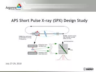
Short X-ray Pulse (SPX) Concept • Proposed by A. Zholents et al in 1999 • Cavity applies transverse field to stored beam before insertion device • Cancelling field applied by second matched cavity after insertion device • Cavities operate at a harmonic of the storage ring frequency 6th Workshop on CW and High Average Power RF
Predicted X-ray Pulse Duration • Will produce X-ray pulses of a few picoseconds duration • Fills an experimental need between pulse durations from FELs and those from conventional operation of storage ring insertion devices 6th Workshop on CW and High Average Power RF
Preliminary Tolerances 6th Workshop on CW and High Average Power RF
Purpose of First Amplifier • Support developmental testing of superconducting cavities • Explore achievable phase and amplitude errors • Try out a possible packaging configuration for a one klystron per cavity approach 6th Workshop on CW and High Average Power RF
Packaging Concept • Single, extra width, aluminum framed cabinet mounts klystron, power supplies, and four port circulator based isolator • Potentially exposed high voltages restricted to one chassis with klystron cathode stem projecting inside • High voltage assembly furnished by TDK Lambda and modified by ANL 6th Workshop on CW and High Average Power RF
Operating Frequency • Must be a harmonic of the storage ring frequency • Cryostat must fit in space allowed for possible second insertion device • 2815.5 MHz allows meeting these constraints and gains some advantage from common technology with 2856 MHz APS linac 6th Workshop on CW and High Average Power RF
Klystron Development and Results • Klystron is derived from JLab klystron, scaled up in frequency • “Best effort” tube specified for 3 kW minimum @ 2815.5 MHz • L-3 Communications ran it at 4 kW • Predicted typical values met or exceeded by a reasonable margin except for gain at rated power which is 42dB versus a predicted 32 dB. • Missed the very demanding schedule by 2 weeks after ceramic brazing difficulties • Weakest point is EIA 1.625” coaxial output which is beyond usual ratings at 5 kW 6th Workshop on CW and High Average Power RF
Predicted Klystron Beam Voltage Phase Pushing • First article of the 5 kW, 1497 MHz, JLab klystron was measured by L-3 Communications to have phase pushing 0.05 deg/Volt. Both tubes have four cavities and the same mechanical length. • Projecting that the electrical lengths vary proportionally to frequency, produces an estimated phase pushing for the 2815.5 MHz klystron of 0.094 deg/Volt • Based, on the above data, HVPS ripple of 0.425 v p-p would use up the entire error budget. Desirable values would be an order of magnitude lower. 6th Workshop on CW and High Average Power RF
Isolator Procurement and Results • AFT turned to have a commercial production unit which only required minor retuning to cover a frequency change from 2856 MHz to 2815.5 MHz and rotation of port assignments • We are living with the magic tee end turned in the wrong direction • Delivery was on schedule • Performance is excellent with isolation and return loss both well over 30 dB 6th Workshop on CW and High Average Power RF
HVPS (Unscheduled) Development • HV Power Supply is a lower power derivative of an extra-low ripple design that TDK Lambda Americas described in a PAC07 paper*, using two 15 kW model 1202 basic power supplies instead of the 50 kW model 303 • TDK Lambda accepted a design goal of 0.001% ripple, based on lower voltage and current with no change to the 20 joule stored energy limit • There turned out to be unanticipated development work because the two series of basic power supply use different internal control topologies *A Precision 75KW, 25KV Power System for a Klystron Amplifier; G.L. Bees et al; Proceedings of PAC07, pp 593-595, Albuquerque, NM, USA 6th Workshop on CW and High Average Power RF
HVPS Development Results • The actual ripple results are quite similar to the results in the PAC07 paper for line related and switching frequency ripple. • However, there is also an additional ripple component @ about 10 kHz. • TDK Lambda says that this can’t be eliminated since it is caused by the IC control chip used in the 1202 series. The 303 series does not use that device. 6th Workshop on CW and High Average Power RF
Full load line frequency ripple with higher frequencies superimposed Measured by TDK Lambda Americas 6th Workshop on CW and High Average Power RF
Full load high frequency ripple showing additional component @ ~10 kHz Measured by TDK Lambda Americas 6th Workshop on CW and High Average Power RF
Half load high frequency ripple Measured by TDK Lambda Americas 6th Workshop on CW and High Average Power RF
Effects of the three ripple frequencies • The TDK Lambda Americas system controller makes synchronizing pulses available at 8 different phases. Their goal is to make use of multiple basic power supplies at different phases to minimize the effective combined ripple. • For the SPX application , synchronizing the power supplies supporting the cancelling cavities identically to those supporting the initial deflecting cavities can provide important reductions in differential phase to smaller values than the absolute phase. • If all power supplies are supplied from the same main feed, line frequency phase ripple can also exhibit decreases in differential phase due to matching. • The 10 kHz component appears to be a significant problem , as a hard to match pseudo-random noise. 6th Workshop on CW and High Average Power RF
Heater Power Supply • Off the shelf regulated AC power supply operated in constant current mode • Standard Stangenes isolation transformer • All monitoring on primary side of transformer 6th Workshop on CW and High Average Power RF
Protection Features • Fast RF drive trips: Body over current Klystron reflected over power (before isolator) Klystron forward over power • 5 fully instrumented & protected water flows/temperatures plus 2 other low flow trips • Heater voltage/ current window HV trips • High voltage access interlock 6th Workshop on CW and High Average Power RF
Summary and Initial Conclusion • The klystron amplifier will complete readiness testing by June 2010 and then will be available to support further system developmental testing. • The dual model 1202 HVPS system is clearly not the best version of a TDK Lambda Americas extra-low ripple HVPS system for the SPX application. A version of the 100 kW capable, dual model 303 design described in the PAC07 paper* would be better in both effective ripple performance and cost per cavity. *A Precision 75KW, 25KV Power System for a Klystron Amplifier; G.L. Bees et al; Proceedings of PAC07, pp 593-595, Albuquerque, NM, USA 6th Workshop on CW and High Average Power RF