Download
1 / 40
400 likes | 402 Views
Proposal for MAPMTs as Photodetectors for the LHCb RICH. Franz Muheim University of Edinburgh on behalf of the MAPMT group. Outline. Introduction Multianode Photo Multiplier Tubes R&D Results Baseline Design Conclusion. Photo Detector Requirements. Photo detector area: 2.9 m 2.

E N D
Proposal for MAPMTs as Photodetectors for the LHCb RICH Franz Muheim University of Edinburgh on behalf of the MAPMT group F.Muheim
Outline • Introduction • Multianode Photo Multiplier Tubes • R&D Results • Baseline Design • Conclusion F.Muheim
Photo Detector Requirements Photo detector area: 2.9 m2 • Single photon sensitivity (200 - 600 nm) with quantum efficiency > 20% • Good granularity: ~ 2.5 x 2.5 mm2 • Large active area fraction: 73% • LHC speed read-out: 40 MHz Options: MAPMT or HPD F.Muheim
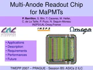
MAPMT Multianode Photo Multiplier Tube • Combines single photon sensitivity with good spatial resolution • 8x8 dynode chains Gain: 3.105 at 800 V • Manufacturer: Hamamatsu • 1 mm flange removed, packing fraction increases by 14 % F.Muheim
MAPMT R7600-03-M64 Quantum efficiency • Bialkali photo cathode, QE = 22% at = 400 nm • UV glass window replaces borosilicate, QE dE increased by 50 % F.Muheim
Quartz Lenses • MAPMT active area fraction: 38% (includes pixel gap) • Increase with quartz lens with one flat and one curved surface to 85% F.Muheim
Bench Tests Pixel scan with LED Single channel spectrum (LED) • Collection efficiency not very uniform (~20%) • Gap between pixels: 0.2 mm • 40 MHz read-out electronics • Average signal/ pedestal width = 40:1 • Signal loss: 11.5 % (includes 2.5% for no multiplication at 1st dynode) F.Muheim
Test Beam Set-up F.Muheim
Single MAPMT Test Beam • CAMAC electronics • RICH 1 prototype Photo electron yield Good agreement F.Muheim
Single MAPMT Test Beam Cherenkov angle resolution • CAMAC electronics • RICH 2 prototype • Focal length: 4 m • Angular resolution • 0.27 mrad (data) • 0.26 mrad (MC) Good agreement F.Muheim
LHC Speed Electronics F.Muheim
LHC Speed F/E Electronics F.Muheim
Test Beam Set-up • Cluster with quartz lenses • Bleeder board • Cluster: 40 MHz Read-out F.Muheim
Cluster Test • 9 MAPMTs read out with 6 boards • 5 threshold cut, common-mode subtracted • Lots of photons, but cross-talk CF4 Radiator, 700 mbar HV = -1000 V F.Muheim
Cross-Talk Probability that pixel y causes hit in pixel x • Asymmetric cross-talk (board 9) • Correlated to neighboring APV Sample channels • Not correlated with neighboring pixels in tube F.Muheim
Cross-Talk Probability that pixel y causes hit in pixel x • Symmetric cross-talk • Correlated with APV input neighbors (ceramic) • Cross-talk source is electronics • MAPMT do not have large cross-talk F.Muheim
Photon Yields With quartz lenses • Cross-talk correction applied • Observe 6.4 photo electrons per event • Background: 0.41 p.e. • Few dead pixels • Yield of different tubes F.Muheim
Photon Yields No lenses Quartz lenses • Ratio with/without lenses = 1.45, expected 1.50 F.Muheim
Photon Yields • Analysis includes • Common-mode subtraction • Cross-talk correction • Background subtraction • Signal loss & dead pixel correction • Results: Preliminary Good agreement F.Muheim
Photon Yields Single events Number of photo electrons F.Muheim
Charged Particles • Charged particles traversing the lens & MAPMT produce background hits • Angle scan F.Muheim
Multiplicities • Multiplicity from charged particles • [5..10] for for most angles • up to 30 for angles around 45o For MAPMTs, charged particles are a small background F.Muheim
Magnetic Field Tests • LED • Pin hole mask • -metal shield • MAPMT tested with • Helmholtz coil • 0, 10, 20, 30 Gauss F.Muheim
No Shielding • MAPMTs are insensitive to transverse magnetic fields up to 30 G • Expect mainly By field • By = 21 ..27 G (RICH 1) • By = 150 G (RICH 2) reduce by ~ 15 with shielding of planes • Sensitive to longitudinal fields 10 G, at 30 G lose 50% top or bottom row (18% average) F.Muheim
With -Metal Shielding • -metal: t = 0.9 mm • Extension: d = 10, 13, 32 mm • Reduced loss at 30 G • 7 .. 25 % worst row (d=10,13 mm) • no structure (d = 32 mm) • Expect low Bz field • Bz = 0 .. 5 G (RICH 1) • Bz = 0 .. 38 G (RICH 2) reduce by ~ 15 with shielding of planes F.Muheim
MAPMT R & D Summary • Successfully tested close-packed 3x3 array of MAPMTs • Quartz lenses work as expected • Measured photon yield in agreement with simulation • Demonstrated 40 MHz read-out Commercial MAPMT fulfils LHCb RICH specifications F.Muheim
Baseline Design Tilted Modules • Pointing geometry • 4x4 array, 1024 channels • Bleeder board with 8 F/E chips • -metal shield • Pixel size at lens: 3.0 x 3.0 mm2 • Filling factor: 0.79 F.Muheim
Half Planes RICH 1 RICH 2 • Total 232 modules, 3504 tubes • Outermost modules only partially equipped • = 440 mrad • 5 columns • 10 rows • = 240 mrad • 6 columns • 11 rows F.Muheim
Integration MAPMT geometry RICH 1 integration • MAPMT pitch: 26.7 mm • Module pitch: 108.8 mm • -metal shield: 0.4 mm • Mounting frame: carbon fibre, G10 • Little distance between Vertex tank and RICH 1 Tracker 1 must also fit • Cooling for 8.8 W /module MAPMT RICH 1 Vertex tank F.Muheim
F/E Electronics Single photon signal: 300’000 e • Characteristics • Spread: 3 • Signal/pedestal width: 60:1 • Dynamic range: 3 photons 5000 … 1’560’000 e • Attenuation: 6 • F/E chip input: • Noise/ dynamic range: 833 ... 260’000 e • ADC bits: 9 • Occupancy: 3 % F.Muheim
F/E Electronics Baseline • APVm chipnot suitable (shaping time) • SCTA128 is baseline (analogue) • Changes necessary to existing chip • Back-end (32 multiplexing), same as for the vertex detector • Gain adaptation for MAPMT signals, attenuation, additional work • Alternative:BEETLE chip • when it becomes available F.Muheim
L0 & L1 Electronics • Level 0: • # of modules / # of chips: 232 / 1856 • # of channels per module: 1024 • # of channels total: 224256 • # of data links: 7424 • Level 1: • Bandwidth (3% occ.) 85/7.7 Gbits/s with/ without Zero suppression • # of VME modules: 78 • # of multiplexers: 5 F.Muheim
Performance • Performance study Guy Wilkinson • Preliminary results: • Identification efficiencies • : 86 %, K : 87 % • Fake rates • : 1.4 %, K : 3.0 % F.Muheim
Schedule • Photo detectors must be ready by 1/7/2004 • Testing takes 2 years • Must place order by 1/3/2001 • Photo detectors are on critical path • F/E electronics design by 1/10/2000 today 1/7/2004 F.Muheim
MAPMT Test Station • Automated test bench • LED or Laser light source • Optical stages • Measure gain of each tube, pixel scan • HV scan • QE measurements (~10% of tubes) • Monochromator • Calibrated standard • Measure Cherenkov light (~10% of tubes) • source in quartz bar & MWPC F.Muheim
MAPMT Costs Unit cost Cost Subtotal • Tube [kSFr] [kSFr] [kSFr] • MAPMT 0.931 3262 • Lenses 0.070 245 3507 • Level 0 • F/E chip, hybrid 0.200 371 • Motherboard 2.000 464 • TTC, DCS, Data Links 135 970 • Level 1 • 9U VME boards 5.000 390 • Links, crates, MUX, RU, etc 199 589 • Total cost: 5066 F.Muheim
Risk Assessment • Baseline design is very close to what we have already tested • MAPMT photon yield and resolution • LHC speed read-out electronics • Close packing (quartz lenses) • Commercial photo detector • Possible delays, Note: LHCb is tomorrow • Manpower • Cost F.Muheim
Risk Assessment • Performance • Photon yield, angular resolution • Charged particles • Magnetic stray fields • Electronics • Adapt F/E chip • Not on critical path • Stability • Radiation damage • HV F.Muheim
Risk / Improvements • Further improvements possible • 2-3% higher QE is possible (manufacturer) 9 -14 % more photons • Incorporate lens into vessel window 8% more photons • Optical coupling between lens & MAPMT 8% more photons • Use 4 threshold cut Smaller signal loss • Binary electronics Cost savings F.Muheim
Conclusions • Results of the MAPMT R&D program • Device performs according to specifications • LHC speed read-out demonstrated • Baseline design presented • Mechanics, Electronics, Integration • Schedule, Cost is a viable choice as photo detector for MAPMT F.Muheim