Download
1 / 31
340 likes | 595 Views
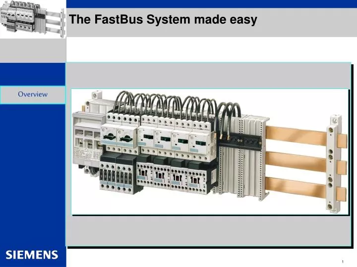
The FastBus System made easy. Overview. The Fast Bus system at a glance.

E N D
The FastBus System made easy Overview
The Fast Bus system at a glance Fast Bus is a 3-phase busbar system for power distribution. The modular design provides the flexibility needed to fit your application. Fast Bus also carries domestic and international approvals, which make it ideal for a global panel design. Fastbus helps provide for quick maintenance, reducing down time.. Adapter shoes can be easily snapped on or removed from the Busbars in seconds and many of the starters and circuit breakers come pre-assembled from Siemens. Overview The Fastbus system can help you save panel space by allowing you to wire and mount circuit protection and motor starters in a tight line. Leave space for future system expansion.
The 8US Fastbus system at a glance Ideal for Large Systems • The Fastbus System reduces installation cost and time by improving mounting density in panels and speeding up installation time with faster mounting and fewer power connections Overview
The Fast Bus system at a glance • Current Ratings • Standard busbar (5 x 20 mm) is UL recognized to 362 Amps @ 600V. • Busbar can be stacked (10 x 20 mm) for high current applications up to 564 Amps @ 600V. • Bracing Ratings (maximum with busbar holder spacing of x inches) • 65kA bracing ratings at 480V at a maximum of 400A. • 42kA bracing ratings at 480V at a maximum of 600A. • 10kA bracing ratings at 600V at a maximum of 600A. Overview • Factory Assemblies for quick installation • SIRIUS 3RA Combination Starters up to 50HP @ 575V • Sentron Circuit Breakers (UL489) up to 250A
The Fast Bus system at a glance Choosing components – Pre-assembled or kitted and ready to go. Overview 3RA11 Non-Reversing and 3RA12 Reversing Combination Starters – Come pre-assembled and ready to place on to the Busbar assembly FBCB***M Fastbus Main Circuit breakers – Offers a full range of Main Circuit Breakers from 100A to 250A pre-packaged with Fastbus adapters and ready for quick assembly FBCB Fastbus Circuit breakers – Offer a full range of Circuit Breakers from 15A to 250A pre-packaged on Fastbus adapters and ready to place on the Busbar FBT250 Three Pole Lug Plate with cover (8US1921-1AA00) 8US1921-1GA00 (FBC84) –Cover for the 8US1921-1A000 Provides terminals for the incoming supply or to jumper from one run of Fast Bus to another.
Designing a Fast Bus System Step Purpose • Determine the total amperage of the required loads • Select method to power Fastbus • Circuit Breaker up to 250A • Main Lug up to 600A • If the sum of the loads is greater than 250A, a separately mounted circuit breaker must be wired to a main lug kit • Select 3RA factory assembled combination starters for each motor load • Select any additional circuit breakers or lugs required to feed non-motor loads or motors greater than 100A • Select appropriate length busbar, busbar support kit(s), insulation covers and any other required components • To decide between 362A and 564A busbar and main lug or circuit breaker • Determines how much busbar space will be taken up by the incoming feed • Determines how much busbar space will be taken up by each starter • Determines how much busbar space will be taken up by each circuit breaker or lug kit • Determines if multiple runs of Fastbus will be required to handle all loads(Note any panel width limitations) Selection
Step 1 – Determine total amperage of required loads Due to the nature of Fast Bus, most applications are considered Group Installation per NEC 430-53 Group Installation is an approach to building multiple motor control systems. In Group Installation, multiple motor starters can be grouped under a short circuit protective device. The 3RA Combination Starters have been UL listed for Group Installation in conjunction with Fast Bus. Selection • Review the specification or line drawing to determine all of the loads in the circuit • Use the calculations below to determine the size to the Short Circuit Protective Device Circuit Breaker Selection - Select a circuit breaker (CB) between: Minimum CB size (per NEC430-110) = Sum of all motor Full Load Currents x 115% Maximum CB size (per NEC430-53c) = 250% x FLC of the largest motor + FLC of all other motors Fuse Selection - Calculate the maximum fuse size per NEC 430-53c: Maximum Fuse size = 175% x FLC of the largest motor + FLC of all other motors
Step 2 – Select Method to Power Fast Bus For Short Circuit Protection from 100 to 250A, we recommend using the FBCB***M Fastbus Main Circuit breakers – These circuit breakers have the Fast Bus wires on the load side. Incoming power wires can be fed through the top of the enclosure directly to the line terminals of the circuit breaker. A Rotary or Max-Flex handle operator can be added to disconnect and lock the breaker in the off position. BreakerRatingWidth FBCB100M 100A 107mm FBCB125M 125A 107mm FBCB150M 150A 114mm FBCB175M 175A 114mm FBCB200M 200A 114mm FBCB225M 225A 114mm FBCB250M 250A 114mm Selection For Short Circuit Protection greater than 250A, use the FBT*** Three Pole Lug Plate assembly with cover – Provides terminals for the incoming supply from a separately mounted Circuit Breaker or Fuse Block. These lug kits could also be used to jumper from one run of Fast Bus to another. Lug Kit RatingWidth FBT250 440A 84mm FBT350 460A 135mm FBT600 560A 135mm
Step 2 – Select Method to Power Fast Bus Working from components – Do it yourself If you want to make the Main Circuit Breaker assemblies using circuit breakers you already have in stock, then you can add the FBS250108M (terminals on bottom for the Main Circuit Breaker) or the FBS250108 (terminals on top for the Feeder Circuit Breaker) FastBus Adapter to your inventory. This adapter will accept E and F frame circuit breakers Selection
Step 3 – Select Combination Starters Starter Selection Process • Non-reversing or reversing motor? • Full Load Current of the motor? • Control Voltage? • Number of auxiliary contacts required on the MSP and on the Contactor? • The 3RA devices can be ordered without any auxiliaries or they can be ordered with one SPDT contact block that plugs in to the top front of the MSP and one NO contact block that mounts to the front of the contactor • We recommend using front mount or plug in auxiliary contact blocks to keep the device width to a minimum • Regardless of which version is ordered, additional auxiliary contacts can always be added in the field • These starters can also be built from stock components. • For quick component selection, use Section 5 of the catalog to select a 3RA factory assembled version. To the right of the 3RA catalog number, you will find a list of the components required for field assembly • To see a detailed visual of how to assemble these starters, see the next page or refer to pages 5/33 through 5/36 of the catalog. Pages 5/6 – 5/9 Non-reversingWidth 3RA111 45 mm 3RA112 45 mm 3RA113 55 mm 3RA114 70 mm Selection Pages 5/14 – 5/17 ReversingWidth 3RA121 90 mm 3RA122 100 mm 3RA123 120 mm
Size 102 (S0) Size 101 (S00) 8US1 5 5 1 1 5 2 1 3RA1921-1. 3 2 2 3 3 3 4 4 Step 3 – Select Combination Starters Working from components – Do it yourself Examples of use 8US1 The two drawing show the use of Sirius size 101 and 102 Combination Starters on an 8US1251-5DM07 Fastbus Adapter (FBS2545) Selection 0 1 1 3RA1911-1A 8US1998-1BA00 Spacer supports a size 101 or 102 contactor to the 8US Fastbus shoe when used with the 3RV MSP
Step 4a – Select Additional Circuit Breakers or lug kits To feed non-inductive loads or motor loads greater than 250A, we recommend using the FBCB*** Fastbus Feeder Circuit breakers – Circuit breakers with Fast Bus wires on the line side. These breakers could feed: • non-inductive loads up to 250 A • motor loads not controlled by an MSP/Contactor combinations (Soft Starters, Drives, NEMA starters) BreakerRatingWidth FBCB015 15A 107mm to FBCB080 80A 107mm FBCB100 100A 107mm FBCB125 125A 107mm FBCB150 150A 114mm FBCB175 175A 114mm FBCB200 200A 114mm FBCB225 225A 114mm FBCB250 250A 114mm Selection To feed circuits with separate short circuit protection up to 440A, use the FBT*** Three Pole Lug kits – Kits of 3 individual lugs used to feed additional circuits or to jumper from one run of Fast Bus to another. Also order the FBCB84 cover to prevent accidental finger contact with the terminals. Lug KitsRatingWidth FBT166-1 180A 12mm ea. FBT122-1 270A 16mm ea. FBT620-1 400A 24mm ea. FBT6250-1 440A 21mm ea. FBT30350 460A 51mm ea. FBT300600 560A 51mm ea. Covers for Lugs FBC84 84 mm FBC135 135 mm 8US1922-1GA02 270 mm Cross Reference Numbers FBT166-1 16-6 AWG 180A = 8US1921-2AA00 1.5 – 16 mm2 FBT122-1 12-2 AWG 270A = 8US1921-2BB00 4.0 – 35 mm2 FBT620-1 6-2/0 AWG 400A = 8US1921-2AD00 16.0 – 70 mm2 FBT6250-1 6-250 MCM 440A = 8US1921-2AC00 16.0 – 120 mm2 FBT30350 3/0-350 MCM 460A = 8US1941-2AA01 95.0 – 185 mm2 FBT300600 300-600 MCM 560A = 8US1941-2AA02 150.0 – 300 mm2 FBCB84 Cover 84 mm wide = 8US1922-1GA00 FBC135 Cover 135 mm wide Cover 270 mm wide = 8US1922-1GA02
Step 4b – Select Additional Fastbus Adapters for other control components The 8US Fastbus system offers Adapter Shoes in various sizes so that you can customize your own Fastbus assembly to your application. Some Adapter Shoes come pre-wired and some without wire so that you can size the wire to your needs or attach to another adapter to mount a connecting device. Adapters for Sirius: 101 (S00)and 102 (S0) frame size (45mm width):8US1251-5DM07 Pre-wired (FBS2545) 8US1250-5AM00 Non-wired (FBS0045) 103 (S2) frame size (55mm width):8US1261-5FM08 Pre-wired (FBS5055) 8US1260-5AM00 Non-wired (FBS0055) Long adapter for combination starters: 8US1261-5FP08 Pre-wired (FBS5055L) 8US1260-5AP00 Non-wired 104 (S3) frame size (72mm width): 8US1111-4TM00 Pre-wired (FBS10070) Selection
Step 5a – Determine the required length of busbar • Add the widths of all components that will be mounted to the busbar. Including: • Main Circuit Breaker or Main Lug Kit • 3RA Combination Starters • Feeder Circuit Breakers • Feeder Lug Kits • Adapters to hold other control products • Determine what additional length may be required for future expansion (if any). • Specify required bracing rating for the system to determine if intermediate supports are required. • 65 kA at 480V at 400A max This requires an intermediate support every 13 inches • 42 kA at 480V at 600A max This requires an intermediate support every 13 inches • 10 kA at 600V at 600A max This requires an intermediate support every 27 inches • Add the widths of all intermediate supports and end supports, which are 20 mm each. • Add all distances together to determine total length of busbar required.
Step 5b – Compare busbar length width available Control Cabinet space • Make sure that the required busbar length will fit in your control panel. • If necessary, break the Fast Bus in to multiple runs within the cabinet. • When breaking in to additional runs, be sure to add the additional end supports to your overall length calculation.
Selection of Busbar components • Mounting Components Required: • 1. End Support Kit - FBS400 • Qty.(2) 5SH3533 End Covers • Qty.(2) 5SH3532 Holder for Edge Profile and End Covers • Qty.(2) 8US1923-2AA00 3 Pole Busbar holder with Outside Fixing • 2. Busbar Kit Choices: • A. FBB36 • Qty.(3) 36 inches long x 5mm x 20mm Tinned Copper Busbar • B. FBB60 • Qty. (3) 60 inch long x 5mm x 20mm Tinned Copper Busbar • Qty. (1) FBSXP – Intermediate support kit • C. 8WC5026Cut your own Busbar • 2 Meter x 20mm x 5mm Copper Busbar • Optional Intermediate Support Kit • FBSXP– Intermediate support kit • Qty.(1) 8US1923-2AA00 Busbar holder with Outside Fixing • Qty.(1) 8US1922-1AC00 Endcover • Optional Ground Busbar Kits • FBG36 • Qty.(2) – 5SH3506 - Ground busbar holders • Qty.(1) – 36 inch long x 6mm x 6mm Busbar (135A) • FBG60 • Qty.(2) – 5SH3506 - Ground busbar holders • Qty.(1) – 60 inch long x 6mm x 6mm Busbar (135A)
Selection of Busbar components • Additional Coverings
The 8US Fastbus system at a glance • Modular Design • Flexibility to lockout the starters required (Rather than lock the entire panel down) Increase productivity. • Incoming coordinated and tested Circuit Breakers • No fuses to buy and replace – Decreased downtime and hard wiring costs. • Finger-Safe Protection • Protective channel prevents accidental contact with busbars • Busbar insulation helps to safely leave room for expansion
Fastbus Basics • Basic assembly • What you need to get started: 8US1923-2AA00 Busbar Supports with Outside Fixing, two needed per meter or yard of Busbar • FBS400 • Qty.(2) 5SH3533 End Covers • Qty.(2) 5SH3532 Holder for Edge Profile • Qty.(2) 8US1923-2AA00 Busbar holders with Outside Fixing • Bus Bar Choices • 1. FBB36- Qty.(3) 36 inch long x 5mm x 20mm Tinned Copper Bar • 2. FBB60 – Qty. (3) 60 inch x 5mm x 20mm Tinned CopperBar + Qty. (1) FBSXP – Intermediate support kit (required for >1m system) • 3. 8WC5026 – 2M x 20mm x 5mm Copper Busbar 5SH3532 Holder for the 5SH3531 Partition 5SH3531 slotted partition. Can be attached on top or bottom of 5SH3532 5SH3533 End cover for 3 Busbar System 5SH3534 End Cover for 4 Busbar System
Fastbus Basics Bus Bar Choices 1. FBB36 - Qty.(3) 36 inches long x 5mm x 20mm Tinned Copper Bus Bar 2. FBB60 – Qty. (3) 60 inch x 5mm x 20mm Tinned Copper BusBar + Qty. (1) FBSXP – Intermediate support kit (required for >1m system) 3. 8WC5026 - 2M x 20mm x 5mm Copper Busbar • Basic assembly • View from the side: When assembling the 8US1923-2AA00 Holder, it can be adjusted to fit the size of Busbar you are using. Once the width matches your Busbar the adjustable piece can be locked in place. The 8US1923-2AA00 can be adjusted to hold 12mm x 5 mm Busbar to 30mm x 10mm. 20mm x 5mm Busbar is standard in the US. Busbar can be stacked (20mm x 10mm) for increased current carrying capabilities. 5SH3506 Ground/Neutral busbar holder. The 5SH3506 can be either mounted with the 8US1923-2AA00 (as shown) or it can be mounted separately to allow for extended busbar adapter shoes. 5SH3532 Holder for the 5SH3531 Partition and/or the 5SH3533 (3Pole) and 5SH3534 (4 Pole) end covers 5SH3533 End cover for covering 3 pole Busbar ends
Fastbus Basics Basic assembly 5SH3531 (slotted) or 5SH3528 (closed) Partition should fit snug and flush to the 5SH3533 End Cover as shown. Both are designed to restrict accidental access to live Busbar 5SH3533 End Cover 8WC5020 6mm x 6mm x 2 M Copper Busbar Ground Busbar Kit Choices FBG36 Qty.(2) – 5SH3506- Ground busbar holders Qty.(1) – 36 inch long x 6mm x 6mm Busbar (135A) FBG60 Qty.(2) – 5SH3506- Ground busbar holders Qty.(1) – 60 inch long x 6mm x 6mm Busbar (135A) 5SH3506 Ground Busbar Holders
Fastbus Components • 8WC5026 20mm x 5mm Copper Busbar • Available in 2 meter lengths • Rated 362 amps @ 600VAC for UL/CSA • Rated 564 amps with Double busbars • FBB36 - Qty.(3) 36 inches long x 5mm x 20mm Tinned Copper Bus Bar • FBB60 – Qty. (3) 60 inch x 5mm x 20mm Tinned Copper BusBar + Qty. (1) FBSXP – Intermediate support kit (required for >1m system) Overview • Wiring Terminals • 3 terminals with covers for wire sizes 16 - 2 AWG • Individual terminals for wire sizes 16 - 250 MCM • 3-pole lug plate with cover for wire sizes 2 - 250 MCM and 3/0 - 600 MCM
Fastbus Basics Ease of use with 8US Fastbus Examples of use Adding and removing Busbar adapters made easy… Adapter Mounting Adapter removal When stacking two Busbar together for increased current ratings the tabs of the Busbar adapter connectors can be broken off to fit 10mm thick Busbar Simply place the adapter over the Busbar and push down until adapter locks in place When removing the Fastbus Adapter from the Busbar, push in the Locking tab on the bottom of the Shoe and push the adapter upwards
Fastbus Basics Group Installation according to NEC 430.53 One of the most common uses for Fastbus is multi-motor applications. Fastbus offers a great solution when applied in accordance with National Electric Code section 430.53. We offer a full line of Main Circuit Breakers from 100 A to 250 A mounted on Fastbus shoe adapters. Since our 3RV Motor Starter Protectors are listed for Group Installation they eliminate the need for an additional branch circuit protector for each motor 3RA11 Combination Starters can be used for Single Motor Taps in accordance with NEC 430.53 (D) (3) since the 3RV Manual Motor Controller’s are labeled “Suitable for Tap Conductor Protection in Group installations” as well as Listed for Type E when using the 3RV1928-1H or 3RT1946-4GA07 Busbar cover for covering open Busbar Branch Circuit Breaker for Power Transformer Main Circuit Breaker feeding the Busbar Assembly sized according to NEC 430.52
Fastbus Basics Here is a good example of how to control multiple motor loads using Fastbus Multiple Busbar runs can be connected by using the 8US1921-1AA00 Three Pole Lug Plate assembly
Advantages of Siemens Fastbus System • Initial Build Cost Savings • Future Expansion Cost Savings • Mean Time To Repair Savings • Technical Benefits
Commercial Savings: B.O.M (Standard Panel Vs Fastbus) Standard Panel SIEMENS Panel Savings of $134.18 (22%) per panel * Information taken from Customer case study
Commercial Savings: Panel Build Labor • Standard Panel • Install 3 Fuse blocks 1.5 Hours • Install Starters 1.5 Hours • Install Disconnect 0.5 Hours • Install PDB 0.5 Hours • Install Plexiglas 1.0 Hours • Total 5 Hours • SIEMENS Panel • Install Busbars 1.0 Hour • Install Starters 0.5 Hours Install Breaker 0.5 Hours • Total 2 Hours At $30/Hour – Savings of $90 per Panel * Information taken from Customer case study
Commercial Savings: Panel Space Standard Panel SIEMENS Panel * Information taken from Customer case study
Commercial Savings: Mean Time To Repair Example Siemens Panel Respond to Fault 15 min Identify Fault 2 mins Total downtime 17 mins • Standard Panel • Respond to Fault 15 mins Identify blown fuse 5 mins Locate Spare Fuse 10 mins Replace fuse 10 mins (Plexiglas) • Total downtime 40 Mins • Worst case Tripped Breaker / Blown Fuse. • Approx $20,000 per minute downtime results in $460,000 savings. * Information taken from customer case study