Download
1 / 21
210 likes | 452 Views
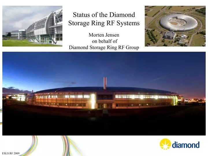
Status of the Diamond Storage Ring RF Systems. Morten Jensen on behalf of Diamond Storage Ring RF Group. ESLS RF 2009. Diamond Storage Ring RF Plant. RFTF. Cryogenic Plant. HV PSU. Circulator and load. Superconducting Cavities. LLRF , DAs and Aux Supplies. IOTs and Combiner.

E N D
Status of the Diamond Storage Ring RF Systems Morten Jensen on behalf of Diamond Storage Ring RF Group ESLS RF 2009
Diamond Storage Ring RF Plant RFTF Cryogenic Plant HV PSU Circulator and load Superconducting Cavities LLRF , DAs and Aux Supplies IOTs and Combiner ESLS RF 2009
Operating Statistics MTBF of RF systems and number of trips MTBF up by factor of 4 MTBF per run; Number of Trips 2008 2009 Typical MTBF as ~20 hrs dominated by cavity 2 trips From Run 2 2009, MTBF increased, cavity 2 trips ~ ½ of all trips MTBF of last 4 runs (since ~ May ‘09) = 80 hrs for all SR RF systems incl cryo Repeat faults include: cavity, arc detection and IOTs. ESLS RF 2009
Cavity coupler still suffer from occasional trips Pulse conditioning indicates presence of MP band ESLS RF 2009
Installation of fast Data Acquisition • Fast data acquisition system based on National Instruments PXI platform • Use of three 60 MHz, 8 channel oscilloscope cards. • Control of external oscilloscope • Control of ‘slow’ acquisition of temperatures and pressures • Simultaneous data acquisition with all channels synchronised. ESLS RF 2009
Installation of fast Data Acquisition Close up of fast signal on e- pickup ESLS RF 2009
MP signal is typically observed 10-20 μs before complete loss of field. Is it possible to detect the onset of multipactor, drop the RF to break the MP condition, re-apply RF hard to re-establish cavity field amplitude and phase without loosing the electron beam? Interruption of RF signal for 10 μs is possible without loss of beam. Design underway of fast trigger circuit to detect MP pulse RF drive to the cavity will be interrupted for a defined duration. Reflected power signal will be gated for this period. Trial hardware for operations. ESLS RF 2009
300 kW Amplifier Four 80 kW IOTs per system Two systems in operation with users Third system available for RFTF, conditioning and testing. Spares which have not been installed are not included above ESLS RF 2009
IOT Upgrade Project • System 1: TED IOTs • IOT type TH793 and one TH793-1 have been used. • Average IOT life on failure 4300 hrs; 11 failures to date • 1 IOT > 17000 hrs • IOT trips are typical prior to failure. • System 2: E2V IOTs • IOT type IOTD2130 • First IOT removed from operation at 14800 hrs. • IOT tripped twice and was replaced. • Initial indication suggest that IOT will condition back up Conclusion: System 1 upgrade required. Options were: Upgrade to TED TH793-1 including full circuit or Upgrade to E2V IOTD2130 including full circuit Tender exercise started → Upgrade of System 1 to IOTD2130 IOTs ESLS RF 2009
IOT Upgrade Project Build and Assembly of new IOT circuits Split output cavity Single output cavity tuner Before installation of output cavity Coaxial output First new circuit in user operation ESLS RF 2009
LLRF Progress Problem with beam loss during system set up by 360 deg phase rotation • Variation with phase of LLRF readings of Pfwd, Probe confirmed • Variation due to distortion in IQ demodulator chain • 8 phase lookup tables produced • Instability at certain phases → faulty module • Variation of suppression at different phases studied Power vs phase Power variation as the phase is rotated Polar plot of IQ demodulated forward power signal. Distortion clearly visible at the higher input level. x3 improvement from 8-point look up table ESLS RF 2009
Selection of other work RF Bypass for normal Operation LLRF Output Local Display PSU drives relay circuits Additional interlock Pulse generator input Programmable parallel port ESLS RF 2009 Pulse conditioning box designed, built and installed
Selection of other work • Drive amplifier Power monitoring: • local read out • data archiving Design and build of IQ phase modulation to enhance synchrotron oscillation for accelerator physics studies such as low alpha optics FPGA development – phase measurement ESLS RF 2009
FPGA development Initial test set-up PSU Signal generator with phase modulation MO to generate clock signal USB connection to PC ADC converter: ADS 5474 evaluation board FPGA Data capture: TSW1200 by TI ESLS RF 2009
Raw I Q data Calculated phase Phase calculated from Calculated phase Raw I Q data Measurement of RF signal with no deliberate modulation showing drift of the signal generator Measurement of RF signal with 0.001 rad phase modulation Initial phase resolution obtained is better than 0.02 deg RMS before filtering or with 0.007 deg RMS with filtering applied ESLS RF 2009
Cryogenic Plant To PLC Turbine speed readout Frequency to Current O/P Turbine Dewar level Turbine control valve FO to electrical conversion FO cable Problem 1 Intermittent turbine speed sensor miss-reading → Sudden drop in ‘speed’ Gas inlet to turbines opens to 100% under PID control. Dewar level rises indicating increased performance despite ‘low’ speed Danger of running out of gas or overfilling of dewar Changed speed transducer, no more faults to date (fingers crossed). Problem 2 No loss of beam or beam time Reduced refrigeration performance Top Heat Exchanger running warm Temporary fix by additional heating on thermal LN2 interlock Suspect contamination of the LN2 heat exchanger ESLS RF 2009
NLS Gun Design using CST Studio • The cell dimensions and coupling gap are adjusted iteratively for field balance and critical coupling at 1.3 GHz. Axial E field normalised to the maximum field in the first cell for the p mode ESLS RF 2009
S11 of final design 0-mode undercoupled, p-mode critically coupled. • Aluminium test cavity ordered. • Funding approved for Cu cavity. • Bench testing about to start. • Gun test facility under consideration ESLS RF 2009
RF Test Facility • Shielded high power cavity conditioning area • Full PSS control • 300 kW RF power from any of the 3 amplifiers • Integration into the Liquid Helium Refrigerator • Full cavity control system ESLS RF 2009
RF Test Facility ESLS RF 2009
On behalf of the RF Group Morten Jensen Pengda Gu Matt Maddock Peter Marten Shivaji Pande Simon Rains Adam Rankin David Spink Alun Watkins Thank you for your attention! ESLS RF 2009