Download
1 / 9
90 likes | 175 Views
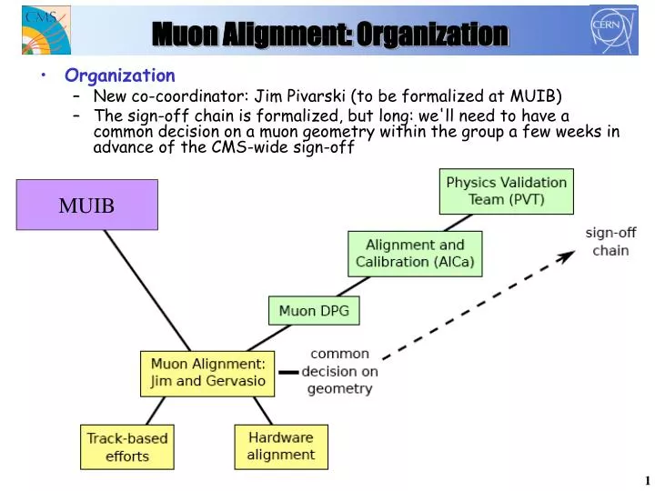
Muon Alignment: Organization. MUIB. Organization New co-coordinator: Jim Pivarski (to be formalized at MUIB) The sign-off chain is formalized, but long: we'll need to have a common decision on a muon geometry within the group a few weeks in advance of the CMS-wide sign-off.

E N D
Muon Alignment: Organization MUIB • Organization • New co-coordinator: Jim Pivarski (to be formalized at MUIB) • The sign-off chain is formalized, but long: we'll need to have a common decision on a muon geometry within the group a few weeks in advance of the CMS-wide sign-off
Muon Alignment: Strategy • “Quasi-static” alignment state • Even when a requested sign-off date is announced in advance, slippage can make the actual date uncertain • To avoid being caught without an agreed-upon geometry, will aim to always have a “state-of-the-art" at hand • The discrepancies/problems that we're working on are usually motivated by the results of validation anyway: having a validated working point formalizes that (and can help assess priorities) • Documentation! • So far largely underused muon alignment Twiki • Aim to document results, validations, tools periodically • Keep documentation updated with respect to “state-of-the-art”
Muon Alignment (quick) Status • Full barrel alignment • All DTs aligned simultaneously • using optical (barrel+link) system • Good agreement of TK-MU relation • between HW and tracks • Decent agreement between track-based • and HW constants • discrepancies under study • First combined HW+track-based • alignments • Validated by PVT • Improved internal DT alignment • Includes theta superlayer • Includes all corner-block-to-wires • and quality control measurements CB f q f • CSC alignment • New beam-halo + photogrammetry alignment • New optical alignment in r-f coordinates • Combined Endcap + Link information • Next step: integration of optical + track-based • alignments
Track-Based Alignment Status I • Unexpected dependence of residuals on position within the chamber (“sawtooth effect”) and on track curvature are now both explained: • Due to a typo, RPC hits were allowed to bias tracker-to-muon propagation • With this corrected, many long-standing mysteries have been resolved • Consequences: • Can lower pT > 100 GeV/c cut used in alignment (see next slide) • Must revise resolution vs. integrated luminosity estimates (“5-20 pb-1 for 200 microns” derived from affected code, likely to be too optimistic)
Track-Based Alignment Status II Residuals are now wider but mean is independent of Pt: can align without high Pt cut
Track-Based Alignment III Removing the RPC-hit bias • Both of these effects had the same cause • All barrel residuals distributions now behave ~ as expected; new alignment produced
Muon Alignment: HW vs Tracks • Chamber-to-chamber agreement at the level of 1.3mm • Outliers in these TB-HW rf difference plots are low-statistics chambers • Largest remaining discrepancy: trend vs. wheel in local-x • Independent of RPC-hit bias • Simple twist model already ruled out by Link and Global and SA track constrains • Other possibilities under study
Muon Alignment: ongoing studies • Track-based analysis: • Confirmed at the level of raw residuals: no sharp breaks at chamber boundaries indicates either a track bias or a coherent rotation of the superplanes • Not proportional to station number, as would be expected of rotated tracks (effect is clearly constant with respect to station number) • Hardware analysis: • End-to-end difference measured by link: 1.1 +- 0.6 mm, not 4 mm as it appears from tracks • Inclinometers and transfer lines can provide additional independent cross-checks • Using independence of the TB/HW datasets to find remaining problems and converge upon a solution
Alignment Constants Time-line 2/7 9/7 16/7 23/7 30/7 6/8 13/8 20/8 27/8 3/9 Agree on common HW runs @ 3.8T CSC HW+B.H. combination studies CSC tracks BH, cosmics, pp Tools for HW Automation Endcap X,Y ME2,3,4 DT tracks Cosmics, pp Barrel Link AR vs. TK Endcap Z, fx ??? Endcap T.L. ??? Optimize HW+Track Combination Integrated HW Geom @ 3.8T Validated HW alignment Validated track alignment Integrated HW + track-based Geom Validated Muon Alignment Geometry Enter “quasi-static” loop (with faster turn-around) New alignment constants due ~ here ?