Download
1 / 9
90 likes | 178 Views
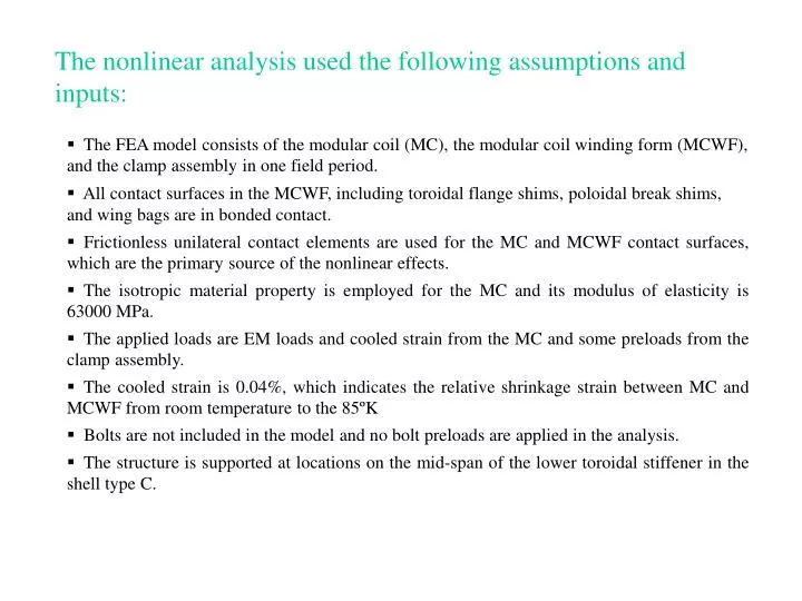
The nonlinear analysis used the following assumptions and inputs:. The FEA model consists of the modular coil (MC), the modular coil winding form (MCWF), and the clamp assembly in one field period.

E N D
The nonlinear analysis used the following assumptions and inputs: • The FEA model consists of the modular coil (MC), the modular coil winding form (MCWF), and the clamp assembly in one field period. • All contact surfaces in the MCWF, including toroidal flange shims, poloidal break shims, and wing bags are in bonded contact. • Frictionless unilateral contact elements are used for the MC and MCWF contact surfaces, which are the primary source of the nonlinear effects. • The isotropic material property is employed for the MC and its modulus of elasticity is 63000 MPa. • The applied loads are EM loads and cooled strain from the MC and some preloads from the clamp assembly. • The cooled strain is 0.04%, which indicates the relative shrinkage strain between MC and MCWF from room temperature to the 85ºK • Bolts are not included in the model and no bolt preloads are applied in the analysis. • The structure is supported at locations on the mid-span of the lower toroidal stiffener in the shell type C.
Shell type A Shell type B Shell type C Shell type C Joint Connections for Toroidal Flange and Poloidal Breaks • Bolts and screws are used on the toroidal flange joints. • Studs use to locate two coils from flanges during assembly are not mechanical fasteners. • The nominal diameter of the bolt or screw is 1.375 inches • Because of the tight flange spacing, there are no bolts available at the inboard flanges. • The number of bolts and screws used at the shell flanges are as follow: 18 bolts and 2 screws at shell joint A-A 24 bolts and 3 screws at shell joint A-B 17 bolts and 12 screws at shell joint B-C, and 24 bolts and 8 screws at shell joint C-C • There are 7 bolts at each poloidal break. The total number of bolt in one field period is 42 bolts
0° 20° Normal Stresses and Shear Stresses for Flange Shim Elements • Three stress Sy, Sxy, and Syz are displayed in the cylindrical coordinate system. • For clarity, contour plots only show the range within -80 MPa and 10 MPa for the normal stress and -16 MPa and 16 MPa for the shear stresses. Stresses outside of the range are in grey color.
40° 60° Normal Stresses and Shear Stresses for Flange Shim Elements (cont'd) • For clarity, contour plots only show the range within -80 MPa and 10 MPa for the normal stress and -16 MPa and 16 MPa for the shear stresses. Stresses outside of the range are in grey color. • Areas with red color in the Sy plot are in tension.
No bolt connection No bolt connection No bolt connection No bolt connection At 20° At 0° At 60° At 40° Inboard Shell Flanges without Bolt Connections • The plots below show the ranges without bolt connection in the inboard flange. • The analysis assumed surfaces are bonded and no relative movement between contact surfaces. • Because of the net EM forces toward the center, the wedge action produces net compression at the inboard. The net forces at the outboard, however, are more in tension. • To prevent the sliding in the areas without bolt connection, the friction forces produced from the compressive forces shall be more than the shear forces.
Net Normal and Shear Forces at Inboard Flange Regions without Bolt Connection • The net forces, in Newton, for the normal and shear forces at the inboard areas are shown in the Tables below: • The total shear force is the vector sum of the horizontal shear and the vertical shear. • The Shear-compression ratios range from 0.123 to 1.003
Type C Type A Type B Type B Type C Type A Contact Pressures on Left Poloidal Breaks • Negative pressure is in tension that should be resisted by the bolt preload. • Unit of contact pressure is Pascal Contact Shear Stresses on Poloidal Breaks • The net compression provided by the bolt preloads shall be able to produce enough frictional forces to withstand the shear forces in the poloidal breaks.
Some factors have effects on the bolted joint loads: The above joint loads are based on the EM loads and the cooling effects of the modular coils on a designated base support locations. Other load cases and structural systems will change the loading at joints. • Interacting forces from the TF coils, PF coils and the vacuum vessel due to dead weight, EM loads, cooling effects and the TF coil preload. • Seismic loads • The locations of the base support structures and the constraints on the supports. • The structural behavior of the TF structure • The support locations for the vacuum vessel.
Options for Improving the joint safety 1) Improving the joint capability • Increasing the coefficient of friction on the contact surfaces. • Adding bolts on the vertical stiffener between toroidal joints. • Using the higher strength bolts up to the allowable bearing stress on the shell 2) Mitigating the joint loads • Reinforcing the TF structure for capable of carrying load in the toroidal direction. • Providing the independent load path for TF and PF loads to the base structure supports. This will simplifies the joint design at the interface and is easier for the FEA analysis. • Designing the joints at the interface of TF structure and shell structure to avoid unexpected loads coming from TF coil preload or TF structure cooling to 85K. • Adding beam underneath the lower TF structure to help spreading the loads. • Adding additional base supports