Download
1 / 51
510 likes | 685 Views
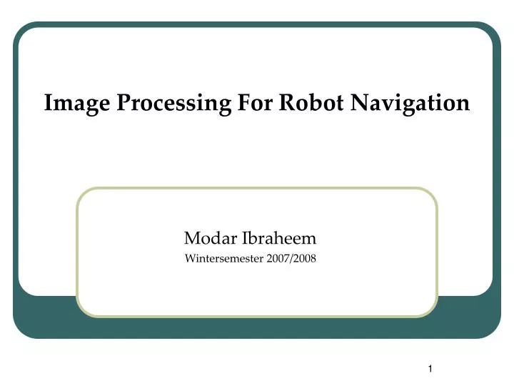
Image Processing For Robot Navigation. Modar Ibraheem Wintersemester 2007/2008. Content. Definitions & Concepts Edge Detection Hough Transform Example. Definitions & Concepts Image.

E N D
Image Processing For Robot Navigation Modar Ibraheem Wintersemester 2007/2008
Content • Definitions & Concepts • Edge Detection • Hough Transform • Example
Definitions & ConceptsImage • An image (from Latin imago) or picture is an artifact, usually two-dimensional, that has a similar appearance to some subject—usually a physical object or a person. • A digital image is a representation of a 2-D image as a finite set of digital values, called picture elements or pixels. • The digital image contains a fixed number of rows and columns of pixels. • Digital images can be created by a variety of input devices and techniques, such as digital Cameras, scanners and more..
Definitions & ConceptsPixel & Bitmaps • A pixel (short for picture element, using the common abbreviation "pix" for "pictures"). • Pixels are the smallest individual element in an image. • Pixels hold quantized values that represent the brightness of a given colour at any specific point. • A digital image is a rectangular array of pixels sometimes called a bitmap. • Color images are made up of colored pixels while black/white images are made of pixels in different shades of gray.
Definitions & ConceptsBlack and White Image • A black and white image is made up of pixels each of which holds a single number corresponding to the gray level of the image at a particular location. • These gray levels span the full range from black to white in a series of very fine steps, normally 256 different grays. • Assuming 256 gray levels, each black and white pixel can be stored in a single byte (8 bits) of memory. • Since the eye can barely distinguish about 200 different gray levels, this is enough to give the illusion of a stepless tonal scale as illustrated here:
Definitions & ConceptsColor Image • A color image is made up of pixels each of which holds three numbers corresponding to the red, green, and blue levels of the image at a particular location. • Red, green, and blue (RGB) are the primary colors for mixing. • Stored in three bytes (24 bits) of memory.
Definitions & ConceptsColor Image • The RGB color model • mapped to a cube. • Values increase along the x- • axis (red), y-axis (green) • and z-axis (blue).
Definitions & ConceptsBits Per Pixel (BPP) • The number of distinct colors that can be represented by a pixel depends on the number of bits per pixel (bpp). • For example, common values are: • 8 bpp ► 256 colors • 16 bpp ► 65536 colors; known as Highcolor or Thousands • 24 bpp ► 16,777,216 colors; known as Truecolor or Millions • 48 bpp; for all practical purposes a continuous colorspace; used in many flatbed scanners and for professional works.
Definitions & ConceptsHistogram • Useful to graphically represent the distribution of pixel values in a histogram. • The histogram of an image represents the relative frequency of occurrence of the various grey levels in the image. • Plots the number of pixels in the image (vertical axis) with a particular brightness value (horizontal axis). • Histogram modeling is the basis for numerous powerful spatial domain processing techniques, especially for image enhancement.
Definitions & ConceptsEdges • set of connected pixels that line one the boundary between two regions. • Candidate points for edges in the image are usually referred to as edge points, edge pixels, or edgels. • Method of edge detection: • Computing the 1st derivative. • Computing the 2st derivative. • Thersholding.
Definitions & ConceptsEdges • Extracting Edges from Images: Many edge extraction techniques can be broken up into two distinct phases: • Finding pixels in the image where edges are likely to occur by looking for discontinuities in gradients. • Linking these edge points in some way to produce descriptions of edges in terms of lines, curves etc.
Edge DetectionOrigin of Edge surface normal discontinuity depth discontinuity surface color discontinuity illumination discontinuity • Edges are caused by a variety of factors
Edge DetectionImages and intensity gradients • The image is a function mapping coordinates to intensity f(x,y). • The gradient of the intensity is a vector. • We can think of the gradient as having an x and a y component.
Edge DetectionSobel Operator-Formulation • The Sobel edge detector uses a pair of 3x3 convolution masks. • Kx estimates the gradient in the x-direction (columns) • Ky estimating the gradient in the y-direction (rows). • * here denotes the 2-dimensional convolution operation. • At each point in the image, the resulting gradient approximations can be combined to give the gradient magnitude.
Hough TransformBasic Idea • Each straight line in the image can be described by an equation. • Each white point if considered in isolation could lie on an infinite number of straight lines. • In the Hough transform each point votes for every line it could be on. • The lines with the most votes win. • Advantage: The Hough Transform can detect lines or curves that are very broken (after initial edge detection, for example). • Disadvantage: HTs can only detect lines or curves that analytically specifiable, or that can be represented in a template-like form (GHT, Ballard).
Hough TransformHow do we represent lines? • Here we will represent the yellow line by (d,) • θ is bounded by [0, 2π] • d is bounded by the diagonal of the image. • This space called Hough space
Hough TransformHow does a point vote? • One point in image space corresponds to a sinusoidal curve in image space. • Two points correspond to two curves in Hough space. • The intersection of those two curves has “two votes”. • This intersection represents the straight line in image space that passes through both points.
Hough Transform Basic Algorithm • Basic Hough transform algorithm • H[d, ]=0 • for each edge point I[x,y] in the image for = 0 to 180 H[d, ] += 1 • Find the value(s) of (d, ) where H[d, ] is maximum.
Hough Transform Outline • Classical Hough Transform • Problem -> Transform to another domain -> solve -> de-transform • Lines generated by the Hough transform are infinite in length. • Detect feature boundaries which can be described by regular curves. • Robustness to noise. • Sensitivity to gaps in the feature boundary. • Generalized Hough Transform • Used when the shape of the feature that we wish to isolate does not have a simple analytic equation describing its boundary. • High computational complexity.
160x120 RGB Grayscale Gaussian filter Thinning Thresholding Sobel detector Corridor Recognition AgentExample The First Step – Image Segmentation
Final Result Corridor: YES Wall: NO Obstacle: NO Corridor Recognition AgentExample The Second Step – Feature Extraction • The HAT is used for extracting the line segments of a corridor path. • How do we extract lines whichbest represent the hallway? • To steps: • Selection • Verification
Final Result Corridor: YES Wall: NO Obstacle: NO Corridor Recognition AgentExample The Second Step – Feature Extraction 1. Selection • Lines whose slop does not fit the geometry constraint are thrown out first. • Each line is compared with the edge maps. • The pixels of a line matching the corresponding edge points are counted. • And only lines with the matching pixels that go above a certain thershold are selected
Corridor Recognition AgentVerification • Verification of the Selected path. • The robot double-checks the lines to see if they really represent the hallway by performing a complete histogram analysis. • On the right, typical patterns of histogram representing the environment of (corridors, walls, objects) 1. The moderate peaks represent the floor. 2. Homogeneously colored object 3. Moderate intensity distribution but the pixels are apt to belong to the tips of gray level.
Thank you for your attention… Quastions?