Download

1 / 35
350 likes | 365 Views
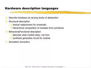
E85 Digital Design & Computer Engineering. Lecture 6: Hardware Description Languages: Verilog. Lecture 6. Introduction Combinational Logic Structural Modeling Sequential Logic. Hardware description language (HDL): specifies logic function only

E N D
E85 Digital Design & Computer Engineering Lecture 6: Hardware DescriptionLanguages: Verilog
Lecture 6 • Introduction • Combinational Logic • Structural Modeling • Sequential Logic
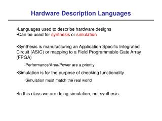
Hardware description language (HDL): specifies logic function only Computer-aided design (CAD) tool produces or synthesizes the optimized gates Most commercial designs built using HDLs Two leading HDLs: SystemVerilog developed in 1984 by Gateway Design Automation IEEE standard (1364) in 1995 Extended in 2005 (IEEE STD 1800-2009) VHDL 2008 Developed in 1981 by the Department of Defense IEEE standard (1076) in 1987 Updated in 2008 (IEEE STD 1076-2008) Introduction
HDL to Gates • Simulation • Inputs applied to circuit • Outputs checked for correctness • Millions of dollars saved by debugging in simulation instead of hardware • Synthesis • Transforms HDL code into a netlist describing the hardware (i.e., a list of gates and the wires connecting them)
HDL to Gates • Simulation • Inputs applied to circuit • Outputs checked for correctness • Millions of dollars saved by debugging in simulation instead of hardware • Synthesis • Transforms HDL code into a netlist describing the hardware (i.e., a list of gates and the wires connecting them) • IMPORTANT: When using an HDL, think of the hardware the HDL should implies
SystemVerilog Modules SystemVerilog Module • Two types of Modules: • Behavioral:describe what a module does • Structural:describe how it is built from simpler modules
Behavioral SystemVerilog SystemVerilog: module example(input logic a, b, c, output logic y); assign y = ~a & ~b & ~c | a & ~b & ~c | a & ~b & c; endmodule
Behavioral SystemVerilog SystemVerilog: module example(input logic a, b, c, output logic y); assign y = ~a & ~b & ~c | a & ~b & ~c | a & ~b & c; endmodule • module/endmodule: required to begin/end module • example: name of the module • Operators: • ~: NOT • &: AND • |: OR
HDL Simulation SystemVerilog: module example(input logic a, b, c, output logic y); assign y = ~a & ~b & ~c | a & ~b & ~c | a & ~b & c; endmodule
HDL Synthesis SystemVerilog: module example(input logic a, b, c, output logic y); assign y = ~a & ~b & ~c | a & ~b & ~c | a & ~b & c; endmodule Synthesis:
Case sensitive Example:reset and Reset are not the same signal. No names that start with numbers Example: 2mux is an invalid name Whitespace ignored Comments: // single line comment /* multiline comment */ SystemVerilog Syntax
Structural Modeling - Hierarchy module and3(input logic a, b, c, output logic y); assign y = a & b & c; endmodule module inv(input logic a, output logic y); assign y = ~a; endmodule module nand3(input logic a, b, c output logic y); logic n1; // internal signal and3 andgate(a, b, c, n1); // instance of and3 inv inverter(n1, y); // instance of inv endmodule
Bitwise Operators module gates(input logic [3:0] a, b, output logic [3:0] y1, y2, y3, y4, y5); /* Five different two-input logic gates acting on 4 bit busses */ assign y1 = a & b; // AND assign y2 = a | b; // OR assign y3 = a ^ b; // XOR assign y4 = ~(a & b); // NAND assign y5 = ~(a | b); // NOR endmodule // single line comment /*…*/ multiline comment Synthesis:
Reduction Operators SystemVerilog: Synthesis: module and8(input logic [7:0] a, output logic y); assign y = &a; // &a is much easier to write than // assign y = a[7] & a[6] & a[5] & a[4] & // a[3] & a[2] & a[1] & a[0]; endmodule
Conditional Assignment SystemVerilog: Synthesis: module mux2(input logic [3:0] d0, d1, input logic s, output logic [3:0] y); assign y = s ? d1 : d0; endmodule ? :is also called a ternary operator because it operates on 3 inputs: s, d1, and d0.
Internal Variables SystemVerilog: Synthesis: module fulladder(input logic a, b, cin, output logic s, cout); logic p, g; // internal nodes assign p = a ^ b; assign g = a & b; assign s = p ^ cin; assign cout = g | (p & cin); endmodule
Precedence Highest Lowest
Numbers Format: N'Bvalue N = number of bits, B = base N'B is optional but recommended (default is decimal)
Bit Manipulations: Example 1 assign y = {a[2:1], {3{b[0]}}, a[0], 6'b100_010}; // if y is a 12-bit signal, the above statement produces: y = a[2] a[1] b[0] b[0] b[0] a[0] 1 0 0 0 1 0 // underscores (_) are used for formatting only to make // it easier to read. SystemVerilog ignores them.
Bit Manipulations: Example 2 SystemVerilog: Synthesis: module mux2_8(input logic [7:0] d0, d1, input logic s, output logic [7:0] y); mux2 lsbmux(d0[3:0], d1[3:0], s, y[3:0]); mux2 msbmux(d0[7:4], d1[7:4], s, y[7:4]); endmodule
Z: Floating Output SystemVerilog: module tristate(input logic [3:0] a, input logic en, output tri [3:0] y); assign y = en ? a : 4'bz; endmodule Synthesis:
Delays module example(input logic a, b, c, output logic y); logic ab, bb, cb, n1, n2, n3; assign #1 {ab, bb, cb} = ~{a, b, c}; assign #2 n1 = ab & bb & cb; assign #2 n2 = a & bb & cb; assign #2 n3 = a & bb & c; assign #4 y = n1 | n2 | n3; endmodule
Delays module example(input logic a, b, c, output logic y); logic ab, bb, cb, n1, n2, n3; assign #1 {ab, bb, cb} = ~{a, b, c}; assign #2 n1 = ab & bb & cb; assign #2 n2 = a & bb & cb; assign #2 n3 = a & bb & c; assign #4 y = n1 | n2 | n3; endmodule
Delays 1 module example(input logic a, b, c, output logic y); logic ab, bb, cb, n1, n2, n3; assign #1 {ab, bb, cb} = ~{a, b, c}; assign #2 n1 = ab & bb & cb; assign #2 n2 = a & bb & cb; assign #2 n3 = a & bb & c; assign #4 y = n1 | n2 | n3; endmodule
Delays 2 module example(input logic a, b, c, output logic y); logic ab, bb, cb, n1, n2, n3; assign #1 {ab, bb, cb} = ~{a, b, c}; assign #2 n1 = ab & bb & cb; assign #2 n2 = a & bb & cb; assign #2 n3 = a & bb & c; assign #4 y = n1 | n2 | n3; endmodule
Delays 2 module example(input logic a, b, c, output logic y); logic ab, bb, cb, n1, n2, n3; assign #1 {ab, bb, cb} = ~{a, b, c}; assign #2 n1 = ab & bb & cb; assign #2 n2 = a & bb & cb; assign #2 n3 = a & bb & c; assign #4 y = n1 | n2 | n3; endmodule
Delays 4 module example(input logic a, b, c, output logic y); logic ab, bb, cb, n1, n2, n3; assign #1 {ab, bb, cb} = ~{a, b, c}; assign #2 n1 = ab & bb & cb; assign #2 n2 = a & bb & cb; assign #2 n3 = a & bb & c; assign #4 y = n1 | n2 | n3; endmodule
Sequential Logic • SystemVerilog uses idiomsto describe latches, flip-flops and FSMs • Other coding styles may simulate correctly but produce incorrect hardware
always Statement General Structure: always @(sensitivity list) statement; Whenever the event in sensitivity listoccurs, statementis executed
D Flip-Flop module flop(input logicclk, input logic [3:0] d, output logic [3:0] q); always_ff @(posedgeclk) q <= d; // pronounced “q gets d” endmodule Synthesis:
Resettable D Flip-Flop module flopr(input logic clk, input logic reset, input logic [3:0] d, output logic [3:0] q); // synchronous reset always_ff @(posedgeclk) if (reset) q <= 4'b0; else q <= d; endmodule Synthesis:
Resettable D Flip-Flop module flopr(input logic clk, input logic reset, input logic [3:0] d, output logic [3:0] q); // asynchronous reset always_ff @(posedgeclk, posedge reset) if (reset) q <= 4'b0; else q <= d; endmodule Synthesis:
D Flip-Flop with Enable module flopren(input logicclk, input logic reset, input logic en, input logic [3:0] d, output logic [3:0] q); // enable and asynchronous reset always_ff @(posedgeclk, posedge reset) if (reset) q <= 4'b0; else if (en) q <= d; endmodule Synthesis:
Latch module latch(input logicclk, input logic [3:0] d, output logic [3:0] q); always_latch if (clk) q <= d; endmodule Warning: We don’t use latches in this text. But you might write code that inadvertently implies a latch. Check synthesized hardware – if it has latches in it, there’s an error. Synthesis:
Review • General Structure: • always @(sensitivity list) • statement; • Flip-flop: always_ff • Latch:always_latch(don’t use)