Download
1 / 24
280 likes | 410 Views
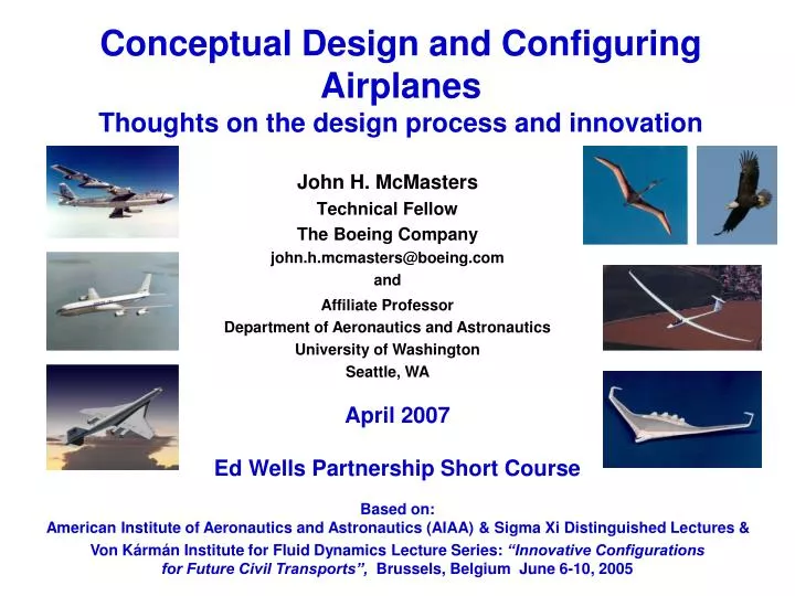
Conceptual Design and Configuring Airplanes Thoughts on the design process and innovation. Affiliate Professor Department of Aeronautics and Astronautics University of Washington Seattle, WA. John H. McMasters Technical Fellow The Boeing Company john.h.mcmasters@boeing.com and.

E N D
Conceptual Design and Configuring AirplanesThoughts on the design process and innovation Affiliate Professor Department of Aeronautics and Astronautics University of Washington Seattle, WA John H. McMasters Technical Fellow The Boeing Company john.h.mcmasters@boeing.com and April 2007 Ed Wells Partnership Short Course Based on: American Institute of Aeronautics and Astronautics (AIAA) & Sigma Xi Distinguished Lectures & Von Kármán Institute for Fluid Dynamics Lecture Series: “Innovative Configurations for Future Civil Transports”, Brussels, Belgium June 6-10, 2005
Airplane Design: Past, Present and Future – • An Early 21st Century Perspective • John McMasters • Technical Fellow • Ed Wells Partnership • The central of several purposes of this course is to examine the co-evolution of our industry, aeronautical technology, and airplane design practice in a broad historical context. Attention then focuses on speculations on possible future trends and development opportunities within an unconventionally broad and multi-disciplinary context. It may then be shown that while aeronautics may be a “maturing industry”, there are numerous opportunities for further advance in our ever-changing enterprise. The emphasis throughout will be concepts and ways of thinking about airplane design in a systems sense rather than on the details of the methodologies one might use in design. The material for this course is a continuing work in progress and represents the instructor’s personal, sometimes idiosyncratic perspective which is in no way intended to reflect an official position of The Boeing Company or its current product development strategy. • Course Objectives: • Provide familiarization to non-specialists on the topics to be discussed • airplane design, • systems thinking, • the value of very broad multidisciplinary inquiry) • Present airplane design and its evolution in a very broad historical context • Present one perspective on a general approach to airplane configuration synthesis at the • conceptual level • Provide a basic aeronautics and airplane design “vocabulary” • Stimulate thought and imagination about the future of aeronautics • Target Audience: • Anyone interested in airplanes and aeronautical technology in a very broad, • multi-disciplinary system sense.
WARNING ITAR and EAR Compliance Important Security Information: Registration for this course (the following notes for which contain no ITAR/EAR-sensitive information) does not enforce the International Traffic in Arms Regulations (ITAR) and Export Administration Regulations (EAR) in any discussions that may result from it. Each attendee is responsible for complying with these regulations and all Boeing policies. EAR/Compliance Home Site: http://policyplus.boeing.com/PS/PDF/DDD/PRO-2805.pdf ITAR/Compliance Site: http://policyplus.boeing.com/PS/PDF/DDD/PRO-174.pdf
A Area (ft.2, m2) a Speed of sound (ft./sec., m/s) AR Aspect ratio, b/č = b2/S b Wing span (ft., m) č Average wing chord (ft.,m) CF Force coefficients (lift, drag, etc.) = F/qS Cℓ Section (2D) lift coefficient CM Moment coefficient = M/qSĉ Cp Pressure coefficient = Δp/q D Drag force (lb., N) E Energy (Ft.-lbs., N-m) e “Oswald efficency factor” ew Wing span efficiency factor (= 1/kw ) F Force (lift, drag, etc.) (lbs., N) H Total head (reservoir pressure) I Moment of inertia kw Wing span efficiency factor (= 1/ew) L Lift force (lb., N) ℓ Length (ft., m) M Mach number (V/a) M Mass (kg) M Moment (ft. lbs., N m) P Power (ft.-lbs./sec., N-m/sec.) p Static pressure (lbs./ft.2) q Dynamic pressure (lbs./ft.2) = ½ρV2 R Range (mi., km) Rn Reynolds number (ρVℓ / μ) S Wing area (ft.2, m2) T Thrust (lb., N) T Temperature (oF) u Local x-direction velocity component V Velocity, Speed (ft./sec., m/s, mph, km/h) v Local y-direction velocity component w Downwash velocity (ft./sec., m/s) ż Sink rate (vertical velocity) (ft./sec., m/s) Greek: α Angle of attack (deg.) Γ Circulation γ Climb or glide angle (deg., rad.) γ Ratio of specific heats in a fluid ε Wing twist angle (deg.) θ Downwash angle (deg.) φ Velocity potential Λ Wing sweep angle (deg.) μ Dynamic viscosity ν Kinematic viscosity (μ/ρ) ρ Fluid mass density (kg/m3) Notation and Symbols Used
Presentation Overview • Conceptual Design and Configuring Airplanes • Thoughts on the design process and innovation
Some VERY Basic Principles in Designing Airplanes • Flying is ultimately about “defying gravity”, thus Weight is generally • the dominant force in designing a good airplane (most of the time). • Historically, the dominant factor in advancing airplane performance • has been engine/propulsion technology [with structures/materials • (and thus weight) and aerodynamics contributing the rest]. • Newton quoth: F = d(mV)/dt To create a given aerodynamic or propulsive force, it’s much better to move a lot of air through • a small ΔV than a lesser amount through a bigger ΔV. Aerodynamic Efficiency (L/D) Wing Weight But Wing span 2/Total exposed area - ( b2 / Swet) Wing Span
A Classic Configuration Comparison(Modified from Torenbeek and Roskam who both got it serious wrong) Boeing B-47 B Avro “Vulcan” B.2 Boeing B-47 Avro Vulcan Max. Take-off Wt. MTOW (lbs.) 202,000 204,000 Ref. Wing area S (ft.2 ) 1,428 3,965 Wetted Surface Area S wet (ft.2 ) 7,070 ~ 9,600 Wing Span b (ft.) 116 111 Aspect Ratio AR (= b2/S) 9.42 3.1 Max. Wing Loading W/S @TO (lb./ft.2 ) 141.5 51.5 Max. Span Loading W/b @TO (lbs./ft.) 1741 1834 Max. Lift/Drag Ratio L/D max ~18.1 ~ 16.8 Evolution of the Boeing B-47
Velocity-Load Factor [V-n] Diagrams Load Factor (n) = Lift (L) / Weight (W) + Max. Maneuver Load [ L = ½ρ V2CLmax S] Load Factor n = L / W Vertical Gust Loads Vmin≈ Vstall 0 Vcruisemax Vdive max Velocity - V - Design and Gust Load conditions per appropriate Regulations (e.g. FARs)
Wing Weight Estimation(based on simple beam theory) Wing span (b) L 2 Lift (L) 2 • Modes of Failure (static or dynamic): • Bending strength • Bending deflection • Torsional strength • Torsional deflection • Buckling • Flutter (either in bending or torsion) U = weight of everything but the wing W = U + Wwing Load factor = n = L W AR = b2/S = b / c avg Total Weight = W ~ U + C[ n U b AR (c/t) ] Є Chord ( c ) Thickness (t)
Trying for the “Ideal” Swept Wingfor a Long-Range Cruising Airplane • Actual wing “length” is different than • the wing span (b). [Length (L) = b sec Λc/4 ] • Defining the “aerodynamically effective” • area of this wing is problematical • Perspectives in Cruise Wing Design • Aerodynamics: • Provide lift required with minimum surface area • Minimum drag at design condition(s) • Acceptable stability and control characteristics • (no “Mach tuck”, pitch-up, etc.) • Compatible with high-lift (take-off and landing) • requirements • Structures & Manufacturing • Adequatethickness (everywhere) • Increasing span is going to cost you • Mostly straight lines and no compound curves • (except maybe parts that can be made of plastic) • Other Folks (Propulsion, Systems, etc.) • Good “rack” for hanging engines from, etc. • Adequate fuel volume • Room for all the actuators and other systems • (e.g. the landing gear) • Management • Minimum cost • Marketable (looks good, etc.) • NOT a subject of endless trade-studies Leading edge glove to minimize “root effects” or allow greater local thickness Straight isobars Λc/4 Tip raked to avoid local “unsweep” effects “Yehudi” Constant shock sweep Wing span (b) (compatible with terminal gate limits)
Area Ruling the Convair F-102 Convair F-106 F-102 Before Area Ruling F-102 After Area Ruling
Subsonic Area Ruling Junkers patent drawing March 1944 Otto Frenzl + Heinrich Hertel Heinrich Hertel 1902-1982 Junkers Ju 287 circa 1944 Heinkel P. 1068 circa 1944 Heinkel P. 1073 circa 1944
Transonic Area Ruling Martin XB-51 Boeing “7X7” circa 1972 Mcruise≈ 0.96 Boeing study circa 1995 Mcruise = 0.95 Blackburn “Buccaneer”
Transonic Tailoring and Kϋchemann “Carrots” Oblique Wing (“ideal” area ruling ) Shockwaves Kϋchemann “carrots” or Whitcomb “speed bumps” Horizontal tail staggered relative to vertical tail Tupolev Tu 20 “Bear” Convair CV 990
Sonic Booms and Their Amelioration(Toward a viable supersonic business jet –SSBJ ?) Bow shock wave Tail wave Modified N-wave ΔP - Classic N-wave sonic boom signature NASA modified F-5E for sonic boom reduction SSBJ concepts Ground footprint of sonic boom
A Summary of Early Progress in Airplane Technology 1900 1910 1920 1930 1940 1950 1960 • Streamlining • Retractable • landing gear • High-lift devices Supersonic flight Airplanes prove their utility in WW 1 Aerodynamics Propulsion Materials & Structures Systems Biplanes to monoplanes Swept wing Boeing B-47 Internal combustion Engines Jet engines Coanda “ducted fan” DeHaviland “Comet” Wood, Steel, Fabric Aluminum airplane (Junkers) Modern air transportation Digital Micro-process Communications & Navigation Aids Parachutes & Safety Systems Pressurization Radar
Future Large “Airplane” Development Opportunities • Civil • Future design must be increasingly efficient, quite, safe, and cost effective. • Military • The B-52 has been operational for 50 years. • Will the B-1 & B-2 remain viable for similar time periods? UCAV replacements?? • Global range logistics will remain a key element in future US foreign policy and peace-keeping. • Aerospace • All “airplanes” must take off and land. Even hypersonic vehicles must be designed for “low-speed” operations. • Non-Traditional • To meet future transportation system needs, new technologies my beexploitable in the 21st century. 787 707 747 767 777 727 A 380 SST ? Airbus 737/A320Replacements DC-8 737 757 737-NG DC-9 DC-10 Blended Wing-Body B-52 B-1 Future Strategic Strike/ Recon. Requirements? B-2 Future Logistics Requirements [ Military and Civil ] C-141 C-5 C-17 X-20 DynaSoar Space Shuttle NASP X-34/X-43 Aerospace Planes ? Ground Transport (Trains, Maglevs, etc.) Surface Effect Vehicles Lighter-Than-Air ? 1960 1980 2000 2020 2040 Year
[Airplane] Design Technology Progress Faster, Farther, Higher Quicker, Better, Cheaper • “Analysis & Testing” • Heavy reliance on testing • Handbooks methods important • Early computational capability • Widening gap between • engineering & manufacturing • “Computation & Validation” • Massive simulation capability • Testing shifts to validation • “Integrated Product Teams” • “Lean” concepts Progress • “Cut & Try” • Heavy on experimentation • Very limited theory • Heavy on rules of thumb • Limited material choice ? Possible Achievement • Issues & Constraints • Cost/profit uber alles • Geopolitical uncertainties • Environmental concerns • Critical resources availability • Lawyers (regulations, litigation, etc.) • All the “-ilities” (old and new) • (reliability, maintainability, etc., etc.) • Customer needs and wants Actual Achievement 1900 1950 2000 WW 2 Berlin Wall Historical Time
Evolution of Airplane Development Process In the beginning (to ~1950) “Small” group of engineers develop a design Skilled craftsmen build it Test Identify a need or opportunity Customer Prototype (Production ) Reqmts. Drawings Orders yes Potential customer(s) no Oblivion
Evolution of Airplane Development Process Maturing phase (~1950 - 1985) Drawings Engineers Design Build Need or Opportunity Test Customer Prototype (Production ) Reqmts. yes Orders Yes No Launch orders no Oblivion Drawings Engineering • Exhaustive • testing • Limited • prototyping • Strong link • between customer, • marketing and • requirements • Regulations, • standards., etc. • Manufacturing • Large • organization • Functional • separation • Large • organization • Functional • separation Lots of paper and bureaucracy
Evolution of Airplane Development Process In the beginning (to ~1950) Engineers Design Build Need or Opportunity Test Customer Drawings Reqmts. Orders ? yes no Modern era (post 1990) Oblivion Outsourcing Acquire “Defineproduce” Support • Up the “value • chain” • No more paper • drawings • No more shims • “Flat(er) • organizations” Customer • “Customer In” • Lots and lots of • lawyers • Engineering & Manufacturing • Large organizations • Integrated Product Teams (IPTs)
What Happens When You Let Electrical Engineers Design Airplanes Lockheed Martin F-117
Evolution of the Airplane Development Process One Possible Option for Our [Immediate] Future Modern era (post 20XX) ? Outsourcing/Risk Sharing Large-Scale System Integration Supplier management Support Acquire Orders “Defineassemble” Test Deliver Requirements ManufacturingEngineering Customer Quicker, Better, Cheaper ?
Changing Times in Aerospace Original Mantra (1903-1990): Faster, farther, higher (and safer). Post Cold War Mantra (1990-2000): Quicker (to market), better, cheaper (and safer). Emerging New Mantra (2001 - ?) Safer, better, faster, higher, farther, cheaper, quicker, quieter, cleaner, etc.. Or: “Leaner, meaner, greener (and safer)” ?