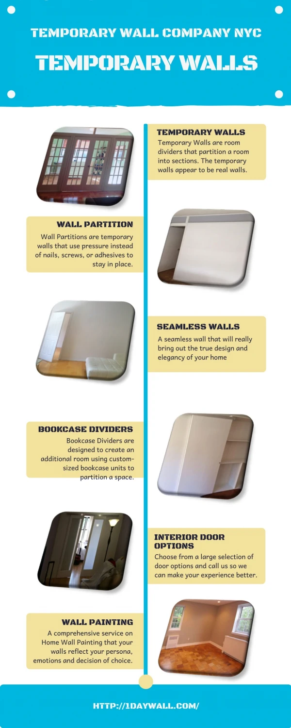
Download
1 / 27
870 likes | 2.13k Views
CM 420 Temporary Structures. Lecture 1. Spring Quarter 2002 University of Washington. CM 420 - Temporary Structures. CM 420 will deal with the materials, methods and techniques associated with temporary structures utilized in various construction operations, such as:

E N D
CM 420Temporary Structures Lecture 1 Spring Quarter 2002 University of Washington
CM 420 - Temporary Structures • CM 420 will deal with the materials, methods and techniques associated with temporary structures utilized in various construction operations, such as: • concrete formwork construction • scaffolding • falsework/shoring • cofferdams • underpinning • diaphram/slurry walls • earth-retaining structures • construction dewatering. • A major emphasis will be placed on concrete formwork construction covering detailed design analysis of both vertical and horizontal timber formwork systems.
CM 420 - Temporary Structures • There will be two midterm exams and three quizzes. • First midterm test will be given on Thursday, April 30th • Second one on Thursday, June 6th. • Grading System: • The course final grade will be calculated based on the following weights: • 25% for homework assignments • 15% for three quizzes • 30% for each midterm exam. • All exams will be closed book.
CM 420 - Temporary Structures Textbooks: • On Reserve: • Hurd, M. K., Formwork for Concrete. 6th edition, American Concrete Institute, Detroit, Michigan, 1995. • Ratay, Robert T., Handbook of Temporary Structures in Construction. 2nd edition, McGraw Hill, New York, 1996.
Formwork for Concrete • Formwork development has paralleled the growth of concrete construction throughout the 20th century. • The increasing acceptance of concrete as a major construction material presents the form builder a new range of problems in the development of appropriate sheathing materials and maintenance of rigid tolerances.
Formwork for Concrete • Formwork is a classic temporary structure in the sense that: • it is erected quickly • highly loaded for a few hours during the concrete placement • and within a few days disassembled for future use. • Also classic in their temporary nature are the connections, braces, tie anchorages, and adjustment devices which forms need.
Formwork for Concrete • The term "Temporary Structures" may not fully imply the temporary, since some forms, tie hardware, and accessories are used hundreds of times, which necessitates high durability and maintainability characteristics and design that maximizes productivity. • Unlike conventional structures, the formwork disassembly characteristics are severely restricted by concrete bond, rigidity, and shrinkage, which not only restricts access to the formwork structure but causes residual loads that have to be released to allow stripping from the concrete which initiates disassembly.
Formwork for Concrete • Lumber was once the predominant form material, but developments in the use of plywood, metal, plastics, and other materials, together with the increasing use of specialized accessories have changed the picture. • Formwork was formerly built in place, used once, and wrecked. • Because of high labor costs in the U.S., the trend today is toward increasing prefabrication, assembly in large units, erection by mechanical means such as “flying” forms into place by crane, and continuing reuse of the forms.
Formwork for Concrete • In 1908 the use of wood versus steel formwork was debated at the ACI convention. Also, the advantages of modular panel forming with its own connecting hardware, and good for extensive reuse were realized. • By 1910 steel forms for paving were being produced commercially and used in the field. A 1909 construction scene shows the first application of steel forms for street paving.
Formwork for Concrete • Today modular panel forming is the norm.
Objectives of Form Building • Forms mold the concrete to desired size and shape and control its position and alignment. • But formwork is more than a mold; it is a temporary structure that supports: • its own weight + • the freshly placed concrete + • construction live loads (including materials, equipment, and personel).
Objectives of Form Building • Basic objectives in form building are three fold: • Quality - In terms of strength, rigidity, position, and dimensions of the forms • Safety - for both the workers and the concrete structure • Economy - the least cost consistent with quality and safety requirements • Cooperation and coordination between engineer / architect and the contractor are necessary to achieve these goals.
Objectives of Form Building • Economy is a major concern since formwork costs constitutes up to 60 percent of the total cost of concrete work in a project. • In designing and building formwork, the contractor should aim for maximum economy without sacrificing quality or safety.
How Formwork Affects Concrete Quality • Size, shape, and alignment of slabs, beams, and other concrete structural elements depend on accurate construction of the forms. • The forms must be: • Sufficiently rigid under the construction loads to maintain the designed shape of the concrete, • Stable and strong enough to maintain large members in alignment, and • Substantially constructed to withstand handling and reuse without losing their dimensional integrity. • The formwork must remain in place until the concrete is strong enough to carry its own weight, or the finished structure may be damaged.
Causes of Formwork Failure • Formwork failures are the cause of many accidents and failures that occur during concrete construction which usually happen when fresh concrete is being placed. • Generally some unexpected event causes one member to fail, then others become overloaded or misaligned and the entire formwork structure collapses. Formwork collapse causes injuries, loss of life, property damage, and construction delays
Causes of Formwork Failure • The main causes of formwork failure are: • - Improper stripping and shore removal • - Inadequate bracing • - Vibration • - Unstable soil under mudsills*, shoring not plumb • - Inadequate control of concrete placement • - Lack of attention to formwork details. *Mudsill: A plank, frame, or small footing on the ground used as a base for a shore or post in formwork.
Causes of FailureImproper Stripping and Shore Removal • Premature stripping of forms, premature removal of shores, and careless practices in reshoring can produce catastrophic results. Case study: Too early shore removal at Bailey's Crossroads in Virginia (1972): 26-stories + apartment building Forms were supported by floors 7-days old or older Failure occurred on the 24th floor, where it was shored to the 5-day-old 23rd floor. The overloaded 23rd floor failed in shear around one or more columns, triggering a collapse that carried through the entire height of the building.
Causes of FailureInadequate Bracing • The more frequent causes of formwork failure, however, are other effects that induce lateral force components or induce displacement of supporting members. • Inadequate cross bracing and horizontal bracing of shores is one of the factors most frequently involved in formwork accidents. • Investigations prove that many accidents causing thousands of dollars of damage could have been prevented only if a few hundred dollars had been spent on diagonal bracing for the formwork support.
Causes of FailureInadequate Bracing Use of Diagonal Bracing • High shoring with heavy load at the top is vulnerable to eccentric or lateral loading. • Diagonal bracing improves the stability of such a structure, as do guys or struts to solid ground or competed structures.
Causes of FailureInadequate Bracing • The main exhibition floor of the New York Coliseum collapsed when concrete was being placed. • Forms for the floor slab were supported on two tiers of shores. Case study: New York Coliseum Formwork collapse, where rapid delivery of concrete introduced lateral forces at the top of high shoring.
Causes of FailureInadequate Bracing Use of Diagonal Bracing Case study: New York Coliseum • Increased diagonal bracing was added to all remaining shoring, following partial collapse of formwork.
Causes of FailureInadequate Bracing Use of Diagonal Bracing • When a failure occurs at one part, inadequate bracing may permit the collapse to extend to a large portion of the structure and multiply the damage. • Suppose a worker accidentally rams or wheelbarrow into some vertical shores and dislodges a couple of them. This may set up a chain of reaction that brings down the entire floor. • One major objective of bracing is to prevent such a minor accident or failure from becoming a disaster.
Causes of FailureVibration • Forms sometimes collapse when their supporting shores or jacks are displaced by vibration caused by: • passing traffic • movement of workers and equipment on the formwork • the effect of vibrating concrete to consolidate it. • Diagonal bracing can help prevent failure due to vibration.
Causes of FailureUnstable Soil under Mudsills, Shoring not Plumb • Formwork should be safe if it is adequately braced and constructed so all loads are carried to solid ground through vertical members. • Shores must be set plumb and the ground must be able to carry the load without settling. • Shores and mudsills must not rest on frozen ground; moisture and heat from the concreting operations, or changing air temperatures, may thaw the soil and allow settlement that overloads or shifts the formwork. • Site drainage must be adequate to prevent a washout of soil supporting the mudsills.
Causes of FailureInadequate Control of Concrete Placement • The temperature and rate of vertical placement of concrete are factors influencing the development of lateral pressures that act on the forms. • If temperature drops during construction operations, rate of concreting often has to be slowed down to prevent a build up of lateral pressure overloading the forms. If this is not done, formwork failure may result. • Failure to regulate properly the rate and order of placing concrete on horizontal surfaces or curved roofs may produce unbalanced loadings and consequent failures of formwork.
Causes of FailureLack of Attention to Formwork Details • Even when the basic formwork design is soundly conceived, small differences in assembly details may cause local weakness or overstress loading to form failure. • This may be as simple as insufficient nailing, or failure to tighten the locking devices on metal shoring. • Other details that may cause failure are: • Inadequate provisions to prevent rotation of beam forms where slabs frame into them on the side. • Inadequate anchorage against uplift for sloping form faces. • Lack of bracing or tying of corners, bulkheads, or other places where unequal pressure is found.
Planning for Safety • OSHA (Occupational Safety and Health Administration) regulations, ACI recommendations, and local code requirements for formwork should be followed. • Supervision and Inspection • Platform and Access for Workers • Control of Concreting Practices • Improving Soil Bearing and Bracing • Shoring and Reshoring • Relationship of Architect, Engineer and Contractor • Maintaining and Coordinating Tolerances • Preparing a Formwork Specification