Download
1 / 3
80 likes | 233 Views
Velocity / m/s. NBI & ICRH. D. Received scattered radiation. k s. k . Resolved fluctuations. k i. Scattering volume. Incident radiation. Shot 89510 NBI(D) 1500 kW ICRH(H) 1000 kW V resolved R = 1.63 m. V resolved. NBI & ICRH. Sawteeth. NBI & ICRH. CTS geometry.

E N D
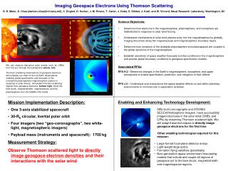
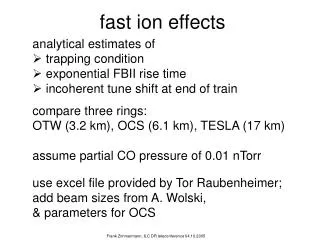
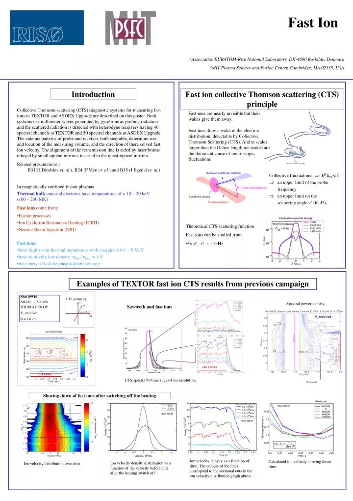
Velocity / m/s NBI & ICRH D Received scattered radiation ks k Resolved fluctuations ki Scattering volume Incident radiation Shot 89510 NBI(D) 1500 kW ICRH(H) 1000 kW V resolved R = 1.63 m V resolved NBI & ICRH Sawteeth NBI & ICRH CTS geometry Ion velocity density as a function of time. The colours of the lines correspond to the sectional cuts in the ion velocity distribution graph above. Calculated ion velocity slowing down time. Ion velocity density distribution as a function of the velocity before and after the heating switch off. Ion velocity distribution over time Fast Ion 1AssociationEURATOM-Risø National Laboratory, DK-4000 Roskilde, Denmark 2MIT Plasma Science and Fusion Center, Cambridge, MA 02139, USA Introduction Fast ion collective Thomson scattering (CTS) principle Collective Thomson scattering (CTS) diagnostic systems for measuring fast ions in TEXTOR and ASDEX Upgrade are described on this poster. Both systems use millimeter-waves generated by gyrotrons as probing radiation and the scattered radiation is detected with heterodyne receivers having 40 spectral channels at TEXTOR and 50 spectral channels at ASDEX Upgrade. The antenna patterns of probe and receiver, both steerable, determine size and location of the measuring volume, and the direction of there solved fast ion velocity. The alignment of the transmission line is aided by laser beams relayed by small optical mirrors, inserted in the quasi-optical mirrors. Related presentations : B31(H.Bindslev et. al.), B24 (F.Meo et. al.) and B35 (J.Egedal et. al.) Fast ions are nearly invisible but their wakes give them away. Fast ions draw a wake in the electron distribution, detectable by Collective Thomson Scattering (CTS). And at scales larger than the Debye length ion wakes are the dominant cause of microscopic fluctuations • Collectivefluctuations kD < 1 • an upper limit of the probe frequency • an upper limit on the scattering angle (ki, ks). • In magnetically confined fusion plasmas • Thermal bulk ions and electrons have temperatures of 10 – 20 keV (100 – 200 MK) • Fast ions come from: • Fusion processes • Ion Cyclotron Resonance Heating (ICRH) • Neutral Beam Injection (NBI) • Fast ions: • have highly non-thermal populations with energies 0.1 – 5 MeV • have relatively low density: nfast / nbulk 1 % • may carry 1/3 of the plasma kinetic energy. Theoretical CTS scattering function Fast ions can be studied from νδ= νs - νi~ 1 GHz Examples of TEXTOR fast ion CTS results from previous campaign Spectral power density. Sawteeth and fast ions CTS spectra 90 time slices 4 ms resolution. Slowing down of fast ions after switching off the heating
Test of the polarizer platesPower measured with the detector for different polarizer angles : min power, : max power. Polarizers Small optical mirror Diode laser Scalar horn Measurement Calculation Detector Design and manufacture of the quasi-optical mirrors at Risø Final quasi-optical mirror Transmission line calculated in Matlab Beams CNC Cutting tools Mirror Cloud of points A detector can be used to measure the antenna pattern The Beam comes from the horn and toward the first mirror CATIA drawing Surface characterization Millimeter Wave CTS Diagnostics on TEXTOR and S. Michelsen1, 2, H. Bindslev1, J. Egedal2, J. A. Hoekzema3,S. B. Korsholm1,2, F. Leuterer4, F. Meo1, P. K. Michelsen1, S.K.Nielsen1, E. L. Tsakadze1, E.Westerhof5and P. Woskov2 3AssociationEURATOM-Forschungszentrum Jülich GmbH, Institut fur Plasmaphysik, 52428 Jülich, Germany Supported by EURATOM and U.S. DoE Email: susanne.michelsen@risoe.dk Web page: www.risoe.dk/euratom/CTS The upgraded CTS system for TEXTOR • The CTS system has been upgraded. The major changes are: • A new quasi-optical transmission line and a motorized steerable mirror • A universal polarizer • Updates in the receiver system: extra amplifiers and a the diplexer which splits the central part of the spectrum from the upper sideband. • A new DAQ system operating 40 channels at 100 k samples/s with a dynamic range of 24 bit. In-vessel mirrors Quasi-optical transmission line for CTS diagnostic Receiver CTS cabinet with electronics Universal polarizer CTS port Steerable mirror Corrugated waveguide Steerable mirror CTS receiver Scattering volume CTS quasi-optical transmission line Container with liquid N2 In front of the horn on the receiver box there is a wire grid, to remove the unwanted polarisation. There is also a chopper mirror which can be inserted when the system is calibrated. Blue parts: upgraded components Alignment of the quasi-optical mirrors Alignment of the system is first done with a diode laser as illustrated on the graph. In this case the polarizer's are covered with a plate containing a small mirror.
T E C MOU box supporting frames Towards the tokamak CTS operation ECRH operation Quasi-optical CTS transmission line CTS receiver and electronics cabinet Moveable mirror is in the neutral position Moveable mirror is in the CTS operation mode ASDEX Upgrade 4Max-Planck-Institut fur Plasmaphysik,EURATOM Association, 85748 Garching, Germany 5FOM-Institute for Plasma Physics Rijnhuizen,Association EURATOM-FOM, Trilateral Euregio Cluster, The Netherlands ASDEX Upgrade CTS system At ASDEX Upgrade, the ECRH system is being upgraded. The CTS system rely on one dual frequency gyrotron at 105 GHz, with 1MW power and a pulse length of 10s. By inserting a moveable mirror in the MOU box, of the other gyrotron, the scattered signal can be redirected into the CTS receiver box. When this mirror is inserted the gyrotron can not be used. This modification of one MOU boxes gives optional use between CTS or gyrotron operation. Modified transmission line for CTS Left: The CTS operation is illustrated, since the mirror is moved into the transmission line. In front of the horn on the receiver box there is a wire grid, to prevent standing waves. There is also a chopper mirror which can be used during calibration of the system. Right: The switching between CTS and gyrotron operation of the beam line is done by a moveable quasi-optical mirror. Calibration setup Horn support Chopper mirror Left: For calibration of the receiver the chopper mirror is used. The black body signal emitted from EchoSorb submersed in liquid N2 is compared with the black body signal at room temperature. Right: An example of the difference in signal for one channel when the chopper mirror is in or out. Container with liquid N2 Receiver Right: The RF part, the IF part, and the filter bank of the receiver for the ASDEX Upgrade CTS system. The RF part consists of notch filters, band pass filter, wideband switch, isolators and a down-converter shifting the centre frequency from 105 GHz to 9.5 GHz. A triplexer divides the signal into three bands: 4.5 – 9.0 GHz, 9.0 – 10.0 GHz, and 10.0 – 14.5 GHz. After a two-step amplification of 70-80 dB the signal enters the 50 channel filter bank. The filter bank and the receiver are located in an aluminium box on top of a cabinet containing DC amplifiers, power supplies, and the data acquisition system, similar to the one at the new TEXTOR CTS system. Summary Present status: The CTS system was installed at ASDEX Upgrade in December 2003 The CTS system for TEXTOR is being upgraded and tested at Risø Future: Commissioning of the CTS systems Physics exploitation of fast ions from NBI and ICRH etc. Design of CTS on ITER is in progress (see posters B31, B24 and B35)