Download

1 / 16
160 likes | 342 Views
8 th progress meeting: EC-ASIC and TEST-EC-ASIC. S. Ahmad, P. Barrillon , S.Blin , D. Cuisy , S. Dagoret - Campagne , P. Dinaucourt , R. Sliwa , JL. Socha October 12 th 2012 - LAL. EC_ASIC history. Week 22: Schematic Week 23-Week 27: Routing

E N D
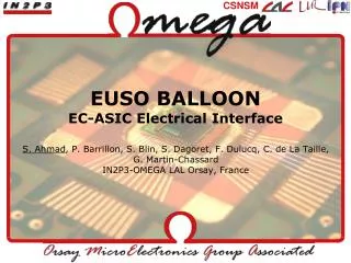
8th progress meeting: EC-ASIC and TEST-EC-ASIC S. Ahmad, P. Barrillon, S.Blin, D. Cuisy, S. Dagoret-Campagne, P. Dinaucourt, R. Sliwa, JL. Socha October 12th 2012 - LAL
EC_ASIC history • Week 22: Schematic • Week 23-Week 27: Routing • Gerber files have been available since 9th July • 1st prototype: • PCB manufacturer: supervised by KIT • Cabling: KIT with ASICs CQFP160 from MATRA • Delivery: 3rd of October • SPACIROC asic tests: July 2012
The ASIC: SPACIROC1 Bonding • Package: CQFP 160pins by MATRA • Received in May: 105 chips • Dedicated test board: • 5 test boards: ok • Firmware and software ok • 3 programs: • Automatic tests • Read out and plot results for one asic • Scan and plot the mean results for all asics
Labview: Automatic test program • List of the tests: • Asic consumption: Avdd, Dvdd • DC measurements: • Bandgap voltage: 2.5V • Pedestals : PA (2.5V), FSU (1V), VFS (1V),KI (1.5V) per channels • DAC linearity: DAC PA, DAC FS, DAC KI • Slow control readout: check srout output • Photon counting tests: Qinj=1/3pe • Scurve versus threshold: trig_pa, trig_fsu • Gain test: scurve versus threshold at different gains • KI tests: • Qinj=2pC/channels, data_ki versus threshold • Threshold defined, data_ki versus input charge for 3 different slow control configurations • 105 asics • Test duration: 6 min • ASICs have to be handled with precaution
Labview: Test resultexample • Results: • 105 asics were tested • Yield: 80% (88% with some a bit noisy) • Enough ASICs for prototypes (2 EC_ASICs), Flight Model (6) and spares (at least 2)
EC_asic board • 1 connector: HIROSE FX2-120P-1.27DS • 120 pins • Header • Right angle type • Through hole TOP VIEW E C A • 6asics SPACIROC1 • Packaging: CQFP 160 pins • 3 on each side • BOTTOM VIEW • 6 connectors: HIROSE FX2CA-68S-1.27DSA • 68 pins (64 analog signals + 4 gnd) • Receptacle • Straight type • Through hole 115 mm 159 mm B F D
EC_ASIC issues • No power consumption: • Probably all bonding wires were broken in the 6 asics • Diodes on the pad weren’t seen • No connection between two pins connected inside the asic (example vdd! pin 120 and pin79) • Soldering temperature cycle at LAL • Steaming (80°C, more than 10 hours) • Oven: 4 temperature steps • With lead: 180,200,221,250°C • ASIC n°174: steaming + two soldering cycles • Asic OK • ASIC n°138: no steaming + one soldering cycle • Asic HS: no bonding • It looks like steaming is mandatory (MATRA agrees) and we probably should go to soldering paste with lead
TEST-EC-ASIC status • Week 27: Schematic • Week 28 – Week 31: Routing • Gerber files have been available since September 5th • 5 test boards have been produced • Company: SOS electronic (France) • Order: 10th September • Delivery: 20th September • Cabling: LAL, week 39 • Firmware is modified by Eric Plaige (LAL) • Software is modified
Connection EC_ASIC and TEST_EC_ASIC EC-ASIC TEST_EC-ASIC regulators Power supply connector 40Mhz oscillator FPGA programmer connectors 120 pin connector USB Lemoconnectors
Development plan • EC_ASIC: • The next week, we will test the EC_ASIC equipped with plastic asics packaged by Riken and cabled at KIT. • MATRA will help us (for free) • They will perform X ray-scan to check the asic bonding on the dead ones • They will remove the 6 asics of 1 EC_ASIC and replace them manually • They will test few (rejected) asics with their standard soldering temperature cycles (lead and lead-free) • TEST_EC_ASIC: • 2 boards have been cabled • Firmware and software have been already modified – debug to be done as soon as we have a working EC_ASIC
The ASIC: SPACIROC (1/3) Spatial Photomultiplier Array Counting and Integrating ReadOutChip • Specifications: • Readout MAPMT signals • Consumption: 1mW/channel • Photon counting: 100% trigger efficiency@50fC (1/3pe, 106 Gain) • Charge/time converter input range : 2pc – 200pc (10pe - 1000pe) • Radiation hardness • 1st version received in October 2010 • Technology: AMS 0.35µm SiGe • Dimensions : 4.6mm x 4.1mm (19 mm²) • Power supply: 0-3V • Packaging : P(C)QFP240(160)
The ASIC: SPACIROC (2/3) • 64 channels • Preamplifier with individual 8-bit gain adjustment • Photo-electron counting (10-bit DACs) • 3 discriminator outputs : Trig_PA, Trig_FSU & Trig_VFS • Multiplexed discriminator outputs to Digital part • Many parameters available • Charge to time converters (called KIs) • Designed in collaboration with JAXA/RIKEN • 9 outputs : 8 channels (8-pixel-Sum) + Last Dynode • Many parameters available • Continuous Data acquisition & Readout every 2.5 ms (GTU) • 8 identical digital module for PC • 1 digital module for KI • First version of SPACIROC showed good behavior (intensive lab tests with and without MAPMT)
The ASIC: SPACIROC (3/3) • Package: CQFP 160pins by MATRA • Quantity: 100 • Cost: 105€/asic • Delay: • Package material : 2 weeks • 3 prototypes: 2 weeks • 100 asics: 2 weeks • One test board has been produced to sort chips • Cabling ok • Firmware is the same as the previous spaciroc test board • Software should be modified to perform automatic tests
EC_ASIC routing constraints • Asic inputs: • Group by 8 consecutive anodes according to the pattern 4 by 2 • No crossing between wires for consecutive layers • Outputs: • Only two routing wires between two connector pins in order to keep a good isolation • More than one layer for the outputs routing • No crossing between inputs and data outputs • LVDS signals • Pay attention to the 40MHz clock • Be careful to power supply planes to minimize the noise spread • Choice to have two layers for gnd and avdd • Maximum isolation on critical signals
Configuration of the EC_ASIC Each ASIC is configured via 898 bits of slow control and 265 bits for the probe set-up. The 6 ASICs of the EC_ASIC are configured in a daisy chain mode, meaning that respectively 5388 and 1590 bits are sent for the slow control and the probes. This daisy chain is done through the signals sr_in and sr_out, the sr_out of one ASIC being the sr_in of the following ones like described in the figure bellow.