Download
1 / 39
400 likes | 815 Views
Computer Logic and Digital Design Chapter 1 Henry Hexmoor. • An Overview of Computer Organization • Switches and Transistors • Boolean Algebra and Logic • Binary Arithmetic and Number Systems • Combinational Logic and Circuits • Sequential Logic and Circuits • Memory Logic Design

E N D
Computer Logic and Digital DesignChapter 1Henry Hexmoor • An Overview of Computer Organization • Switches and Transistors • Boolean Algebra and Logic • Binary Arithmetic and Number Systems • Combinational Logic and Circuits • Sequential Logic and Circuits • Memory Logic Design • The DataPathUnit Henry Hexmoor
Basic Definitions • Computer Architecture is the programmer’s perspective on functional behavior of a computer (e.g., 32 bits to represent an integer value) • Computer organization is the internal structural relationships not visible to a programmer…e.g., physical memory Memory CPU = Control unit + datapath I/O Henry Hexmoor
Application Operating System Compiler Firmware Instruction Set Architecture Instr. Set Proc. I/O system Datapath & Control Digital Design Circuit Design Layout Hierarchy of Computer Architecture High-Level Language Programs Assembly Language Programs Software Machine Language Program Software/Hardware Boundary Hardware Microprogram Register Transfer Notation (RTN) Logic Diagrams Circuit Diagrams Henry Hexmoor
Basic Definitions input output • Architectural levels: Programs and applications to transistors Electrical Signals: discrete, atomic elements of a digital system…binary values… An ideal switch Henry Hexmoor
High Low Digital circuit inputs outputs : : Introduction to Digital Systems • Analog devices and systems process time-varying signals that can take on any value across a continuous range. • Digital systems use digital circuits that process digital signals which can take on one of two values, we call: 0 and 1 (digits of the binary number system) or LOW and HIGH or FALSE and TRUE • Digital computers represent the most common digital systems. • Once-analog Systems that use digital systems today: • Audio recording (CDs, DAT, mp3) • Phone system switching • Automobile engine control • Movie effects • Still and video cameras…. Analog Signal Digital Signal Henry Hexmoor
Eight Advantages of Digital Systems Over Analog Systems • Reproducibility of the results • Accuracy of results • More reliable than analog systems due to better immunity to noise. • Ease of design: No special math skills needed to visualize the behavior of small digital (logic) circuits. • Flexibility and functionality. • Programmability. • Speed: A digital logic element can produce an output in less than 10 nanoseconds (10-8 seconds). • Economy: Due to the integration of millions of digital logic elements on a single miniature chip forming low cost integrated circuit (ICs). Henry Hexmoor
Boolean Algebra What is an Algebra? (e.g. algebra of integers) set of elements (e.g. 0,1,2,..) set of operations (e.g. +, -, *,..) postulates/axioms (e.g. 0+x=x,..) • Boolean Algebra named after George Boole who used it to study human logical reasoning – calculus of proposition. • Elements : trueor false ( 0, 1) • Operations: a OR b; a AND b, NOT a e.g. 0 OR 1 = 1 0 OR 0 = 0 1 AND 1 = 1 1 AND 0 = 0 NOT 0 = 1 NOT 1 = 0 Henry Hexmoor
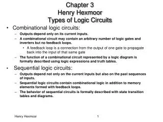
Digital (logic) Elements: Gates • Digital devices or gates have one or more inputs and produce an output that is a function of the current input value(s). • All inputs and outputs are binary and can only take the values 0 or 1 • A gate is called a combinational circuit because the output only depends on the current input combination. • Digital circuits are created by using a number of connected gates such as the output of a gate is connected to to the input of one or more gates in such a way to achieve specific outputs for input values. • Digital or logic design is concerned with the design of such circuits. Henry Hexmoor
x y x y x.y x x+y x' Boolean Algebra • Set of Elements: {0,1} • Set of Operations: {., + , ¬ } NOT OR AND Signals: High = 5V = 1; Low = 0V = 0 Henry Hexmoor
Symbol set 2 (ANSI/IEEE Standard 91-1984) Symbol set 1 a b AND & a.b a b a.b OR a b + a+b a b a+b NOT a a' 1 a a' a b a b (a.b)' & NAND (a.b)' a b a b NOR (a+b)' 1 (a+b)' a b a b EXCLUSIVE OR =1 a b a b Logic Gates Henry Hexmoor
x y x . y x + y 0 0 0 0 0 1 0 1 1 0 0 1 1 1 1 1 Truth Tables • Provide a listing of every possible combination of values of binary inputs to a digital circuit and the corresponding outputs. Truth table • Example (2 inputs, 2 outputs): inputs outputs inputs outputs x x . y Digital circuit y x + y Henry Hexmoor
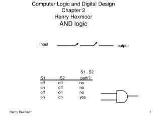
A B A.B Vcc 12 10 9 8 11 14 13 1 2 3 4 5 6 7 Ground Logic Gates: The AND Gate • The AND Gate Truth table Top View of a TTL 74LS family 74LS08 Quad 2-input AND Gate IC Package Henry Hexmoor
A B A+B Logic Gates: The OR Gate • The OR Gate Truth table Top View of a TTL 74LS family 74LS08 Quad 2-input OR Gate IC Package Henry Hexmoor
A B A B (A.B)' x x' (A.B)' Logic Gates: The NAND Gate • The NAND Gate • NAND gate is self-sufficient (can build any logic circuit with it). • Can be used to implement AND/OR/NOT. • Implementing an inverter using NAND gate: Truth table Henry Hexmoor Top View of a TTL 74LS family 74LS00 Quad 2-input NAND Gate IC Package
A B A B (A+B)' (A+B)' x x' Logic Gates: The NOR Gate • The NOR Gate • NOR gate is also self-sufficient (can build any logic circuit with it). • Can be used to implement AND/OR/NOT. • Implementing an inverter using NOR gate: Truth table Top View of a TTL 74LS family 74LS02 Quad 2-input NOR Gate IC Package Henry Hexmoor
A B A B Vcc 12 11 10 9 8 14 13 1 2 3 4 5 6 7 Ground Logic Gates: The XOR Gate • The XOR Gate Truth table Top View of a TTL 74LS family 74LS86 Quad 2-input XOR Gate IC Package Henry Hexmoor
x y F1 z' z Drawing Logic Circuits • When a Boolean expression is provided, we can easily draw the logic circuit. • Examples: F1 = xyz' (note the use of a 3-input AND gate) Henry Hexmoor
A' B' C F4 Analyzing Logic Circuits • When a logic circuit is provided, we can analyze the circuit to obtain the logic expression. • Example: What is the Boolean expression of F4? F4 = (A'B'+C)' A'B' A'B'+C (A'B'+C)' Henry Hexmoor
Integrated Circuits • An Integrated circuit (IC) is a number of logic gated fabricated on a single silicon chip. • ICs can be classified according to how many gates they contain as follows: • Small-Scale Integration (SSI): Contain 1 to 20 gates. • Medium-Scale Integration (MSI): Contain 20 to 200 gates. Examples: Registers, decoders, counters. • Large-Scale Integration (LSI): Contain 200 to 200,000 gates. Include small memories, some microprocessors, programmable logic devices. • Very Large-Scale Integration (VLSI): Usually stated in terms of number of transistors contained usually over 1,000,000. Includes most microprocessors and memories. Henry Hexmoor
Computer Hardware Generations • The First Generation, 1946-59: Vacuum Tubes, Relays, Mercury Delay Lines: • ENIAC (Electronic Numerical Integrator and Computer): First electronic computer, 18000 vacuum tubes, 1500 relays, 5000 additions/sec. • First stored program computer: EDSAC (Electronic Delay Storage Automatic Calculator). • The Second Generation, 1959-64: Discrete Transistors. (e.g IBM 7000 series, DEC PDP-1) • The Third Generation, 1964-75: Small and Medium-Scale Integrated (SSI, MSI) Circuits. (e.g. IBM 360 mainframe) • The Fourth Generation, 1975-Present: The Microcomputer. VLSI-based Microprocessors. Henry Hexmoor
Intentionally left blank Henry Hexmoor
Positional Number Systems • A number system consists of an order set of symbols (digits) with relations defined for +,-,*, / • The radix (or base) of the number system is the total number of digits allowed in the the number system. • Example, for the decimal number system: • Radix, r = 10, Digits allowed = 0,1, 2, 3, 4, 5, 6, 7, 8, 9 • In positional number systems, a number is represented by a string of digits, where each digit position has an associated weight. • The value of a number is the weighted sum of the digits. • The general representation of an unsigned number D with whole and fraction portions number in a number system with radix r: Dr = d p-1 d p-2 ….. d1 d0.d-1 d-2 …. D-n • The number above has p digits to the left of the radix point and n fraction digits to the right. • A digit in position i has as associated weight ri • The value of the number is the sum of the digits multiplied by the associated weight ri : Henry Hexmoor
Decimal 0 1 2 3 4 5 6 7 8 9 10 11 12 13 14 15 Hex 0 1 2 3 4 5 6 7 8 9 A B C D E F Binary 0000 0001 0010 0011 0100 0101 0110 0111 1000 1001 1010 1011 1100 1101 1110 1111 Number Systems Used in Computers Name of Radix Radix Set of Digits Example {0,1,2,3,4,5,6,7,8,9} 25510 Decimal r=10 Binary r=2 {0,1} 111111112 {0,1,2,3,4,5,6,7} 3778 Octal r= 8 {0,1,2,3,4,5,6,7,8,9,A, B, C, D, E, F} FF16 Hexadecimal r=16 Henry Hexmoor
Binary numbers • a bit: a binary digit representing a 0 or a 1. Binary numbers are base 2 as opposed to base 10 typically used. Instead of decimal places such as 1s, 10s, 100s, 1000s, etc., binary uses powers of two to have 1s, 2s, 4s, 8s, 16s, 32s, 64s, etc. 1012=(1×22)+(0×21)+(1×20)=410 + 110 = 510 101112=(1×24)+(0×23)+(1×22)+(1×21)+(1×20)=2310 4110 = 41/2 + remainder = 11LSB = 20/2 + remainder = 0 2SB = 10/2 + remainder = 0 3SB = 5/2 + remainder = 1 4SB = 4/2 + remainder = 0 5SB = 2/2 = 1 6SB 1010012 Henry Hexmoor
Largest numbers • the largest number of d digits in base R is Rd- 1 Examples: 3 digits of base 10: 103-1 = 999 2 digits of base 16: 162 -1 = 255 Henry Hexmoor
Decimal-to-Binary Conversion • Separate the decimal number into whole and fraction portions. • To convert the whole number portion to binary, use successive division by 2 until the quotient is 0. The remainders form the answer, with the first remainder as the least significant bit (LSB) and the last as the most significant bit (MSB). • Example: Convert 17910 to binary: 179 / 2 = 89 remainder 1 (LSB) / 2 = 44 remainder 1 / 2 = 22 remainder 0 / 2 = 11 remainder 0 / 2 = 5 remainder 1 / 2 = 2 remainder 1 / 2 = 1 remainder 0 / 2 = 0 remainder 1 (MSB) 17910 = 101100112 Henry Hexmoor
Decimal-to-Binary examples 90/2 = 45 45 * 2 = 90, remainder 0 45/2 = 22.5 22 * 2 = 44, remainder 1 22 * 2 = 44, remainder 0 22/2 = 11 11 * 2 = 22, remainder 0 11/2 = 5.5 5 * 2 = 10, remainder 1 5/2 = 2.5 2 * 2 = 4, remainder 1 2/2 = 1 1 * 2 = 2, remainder 0 1 / 2 = 0 0 * 2 = 0, remainder 1 10110102 7/2 = 3.5 3 * 2 = 6, remainder 1 3/2 = 1 1 * 2 = 2, remainder 1 1/2 = 0 0 * 2 = 0, remainder 1 1112 108/2 = 54 54 * 2 = 108, remainder 0 54 /2 = 27 27 * 2 = 54, remainder 0 27/2 = 13.5 13 * 2 = 26, remainder 1 13 /2 = 6.5 6 * 2 = 12, remainder 1 6/2 = 3 3 * 2 = 6, remainder 0 3/2 = 1 1 * 2 = 2, remainder 1 11011002 11/2 = 5.5 5 * 2 = 10, remainder 1 5/2 = 2.5 2 * 2 = 4, remainder 1 2/2 = 1 1 * 2 = 2, remainder 0 1 / 2 = 0 0 * 2 = 0, remainder 1 10112 Henry Hexmoor
Decimal-to-Hex examples 20/16 = 1 1 * 16 = 16, remainder 4 1/16 = 0 0 * 16 = 0, remainder 1 1416 108/16 = 6.75 6 * 16 = 96, remainder 12 6 /16 = 0 0 * 16 = 0, remainder 6 6C16 32/16 = 2 2 * 16 = 32, remainder 0 2 /16 = 0 0 * 16 = 0, remainder 2 2016 160/16 = 10 10 * 16 = 160, remainder 0 10/16 = 0 0 * 16 = 0, remainder 10 A016 90/16 = 5.625 5 * 16 = 80, remainder 10 5 / 16 = 0 0 * 16 = 0, remainder 5 5A16 Henry Hexmoor
Decimal-to-Octal example 10/8 = 1 1 * 8 = 8, remainder 2 1/8 = 0 0 * 8 = 0, remainder 1 128 108/8 = 13.5 13 * 8 = 104, remainder 4 13/8 = 1 1 * 8 = 8, remainder 5 1 / 8 = 0 0 * 8 = 0, remainder 1 1548 16/8 = 2 2 * 8 = 16, remainder 0 2/8 = 0 0 * 8 = 0, remainder 2 208 24/8 = 3 3 * 8 = 24, remainder 0 3/8 = 0 0 * 8 = 0, remainder 3 308 Henry Hexmoor
Decimal-to-Binary Conversion • To convert decimal fractions to binary, repeated multiplication by 2 is used, until the fractional product is 0 (or until the desired number of binary places). The whole digits of the multiplication results produce the answer, with the first as the MSB, and the last as the LSB. • Example: Convert 0.312510 to binary Result Digit .3125 2 = 0.625 0 (MSB) .625 2 = 1.25 1 .25 2 = 0.50 0 .5 2 = 1.0 1 (LSB) 0.312510 = .01012 Henry Hexmoor
Binary Arithmetic Operations - Addition • Similar to decimal number addition, two binary numbers are added by adding each pair of bits together with carry propagation. • Addition Example: 1 0 1 1 1 1 0 0 0 Carry X 190 1 0 1 1 1 1 1 0 Y + 141 + 1 0 0 0 1 1 0 1 X + Y 331 1 0 1 0 0 1 0 1 1 0 + 0 = 0 0 + 1 = 1 1 + 0 = 1 1 + 1 = 0 with a carry of 1 Henry Hexmoor
95 = 1011111 -16 = 0010000 79 = 1001111 Binary Arithmetic- subtraction 0 – 0 = 0 1 – 0 = 1 1 – 1 = 0 0 – 1 = 1 with a borrow of 1 Henry Hexmoor
Binary Arithmetic Operations: Subtraction • Two binary numbers are subtracted by subtracting each pair of bits together with borrowing, where needed. • Subtraction Example: 0 0 1 1 1 1 1 0 0 Borrow X 229 1 1 1 0 0 1 0 1 Y - 46 - 0 0 1 0 1 1 1 0 183 1 0 1 1 0 1 1 1 Henry Hexmoor
1011 *101 1011 0000 1011 110111 Binary Arithmetic - Multiplication 0 * 0 = 0 0 * 1 = 0 1 * 0 = 0 1 * 1 = 1 Henry Hexmoor
Negative Binary Number Representations • Signed-Magnitude Representation: • For an n-bit binary number: Use the first bit (most significant bit, MSB) position to represent the sign where 0 is positive and 1 is negative. Ex. 1 1 1 1 1 1 1 12 = - 12710 • Remaining n-1 bits represent the magnitude which may range from: -2(n-1) + 1 to 2(n-1) - 1 • This scheme has two representations for 0; i.e., both positive and negative 0: for 8 bits: 00000000, 10000000 • Arithmetic under this scheme uses the sign bit to indicate the nature of the operation and the sign of the result, but the sign bit is not used as part of the arithmetic. Magnitude Sign Henry Hexmoor
Parity bit • Pad an extra bit to MSB side to make the number of 1’s to be even or odd. Sender and receiver of messages make sure that even/odd transmission patterns match Henry Hexmoor
Gray codes • In binary codes, number of bit changes are not constant, 0000010100111001011101111000… bit changes in gray codes are constant 000001011010110111000… Henry Hexmoor
Alphanumeric Binary Codes: ASCII Seven bit codes are used to represent all upper and lower case letters, numbers, punctuation and control characters Henry Hexmoor
HW 1 What is the decimal equivalent of the largest integer that can be represented with 12 binary bits. Convert the following decimal numbers to binary: 125, 610, 2003, 18944. Henry Hexmoor