Download
1 / 32
330 likes | 597 Views
TEL AVIV UNIVERSITY The Iby and Aladar Fleischman Faculty of Engineering The Zandman-Slaner School of Graduate Studies Measuring Ultrasonic Lamb Waves Using Fiber Bragg Grating Sensors By Eyal Arad (Dery) Under the supervision of Prof. Moshe Tur. This study ….

E N D
TEL AVIV UNIVERSITYThe Iby and Aladar Fleischman Faculty of EngineeringThe Zandman-Slaner School of Graduate StudiesMeasuring Ultrasonic Lamb Waves Using Fiber Bragg Grating SensorsByEyal Arad (Dery)Under the supervision of Prof. Moshe Tur
This study… Deals with the detection of propagating ultrasonic waves in plates, used for damage detection. The detection is performed using a fiber optic sensor (specifically, a Fiber Bragg Grating sensor) bonded to or embedded in the plate.
Contents • General Introduction: • Structural Health Monitoring and Non-Destructive Testing • Lamb Waves in NDT • Fiber Bragg Grating Sensors • The goals of this work • Analysis and results • Analytical solutions • Numerical solutions and comparison • Tangentially bonded FBG • Setup and Experimental Results • Effects and implications • Angular Dependence • Rosette Calculations • Summary of Findings • Future Work
General Introduction Structural Health Monitoring (SHM) and Non-Destructive Testing (NDT) • SHM- the process of damage identification (detection, location, classification and severity of damage) and prognosis • SHM Goal- increase reliability, improve safety, enable light weight design and reduce maintenance costs • NDT- an active approach of SHM • Several NDT techniques exist, among them is Ultrasonic Testing • Many Ultrasonic Testing techniques for plates utilizes Lamb Waves in a Pulse- Echo method (damage= another source) • Usually, both transducer and sensor are piezoelectric elements
Lamb Waves Implementations in NDT • Lamb waves are Ultrasonic (mechanic) waves propagating in a thin plate (thickness<<wavelength) • Important characteristics for NDT: • Low attenuation over long distances • Velocity depends on the frequency (could be dispersive) • Creates strain changes that can be detected
Lamb Waves Implementations in NDT • Some examples for suggested implementationsin the aerospace field: • Qing (Smart Materials and Structures, v.14 2005) • Kojima (Hitachi Cable Review, v. 23, 2004)
Lamb Waves Propagation • In infinite material 3 independent modes of displacement exist • In thin plates the x and y displacements are coupled (boundary conditions) and move together • Two types of modes exist: • Symmetric waves(around x) • Antisymmetric waves
Lamb Waves Propagation • Plane wave (infinite plate) • Symmetric waves (displacement) Where ξis the wave number ω/vph, and α,β are proportional to the material’s constants • Antisymmetric waves α,β
Lamb Waves Propagation • Cylindrical Lamb wave • In the area close to the transducer • Symmetric case • H0 and H1 are Hankel Function of zero and first kind. • For the antisymmetric solution it is only necessary to interchange sinh and cosh
Lamb Waves Propagation • Dispersion relations (Vph(f)): • Lamb wave modes • The selected working mode is A0
Fiber Bragg Grating (FBG) Sensors • Permanent, periodic perturbation of the refractive index • λB=2neffΛ • Reflection curve • Measuring Ultrasound according to:
FBG’s advantages for NDT: • Directional Sensitivity • Small Size • Fast Response – up to several MHz • Ability to Embed inside Composites • EMI, RFI Immunity • Ability to Multiplex (several sensors on the same fiber)
Summary of Introduction • SHM & NDT concept and goal • Lamb waves and their importance to NDT • FBG principle and advantages in NDT
Purpose of This Study • To build an analytical model for a pulse of propagating Lamb wave, in order to validate a Finite Element (numerical) model, for applying on complex cases which cannot be solved analytically. • To analyze the behavior of the detected ultrasonic signal at close range to the transducer, where the wave is cylindrical. • Extending published plane wave analysis, to analyze the effect of close range sensing on the angular dependence of FBGs and on angle-to-source calculations.
Analysis and Results Lamb Wave Solutions for a Pulse Input • Input: single period sine function pulse • Plane wave A0: • x=0 Using inverse Fourier transformto convert to the time domain A0 plane wave displacements ux (blue) and uy (green) vs. time at x=0 and y=b
watch Lamb Wave Solutions for a Pulse Input • For all x (Plane wave A0) • Dispersion relation- A0 is dispersive Dispersion relation for A0 (blue) and S0 (black) ux displacements of A0 at distances of 0 (blue), 10(green), 20 (red) and 30cm (cyan) uy displacements of A0 at distances of 0 (blue), 10(green), 20 (red) and 30cm (cyan)
watch Lamb Wave Solutions for a Pulse Input • Cylindrical Lamb wave ur displacements of A0 at r= PZT edge (blue), 5 (green), 10 (red) and 20cm (cyan) uz displacements of A0 at r= PZT edge (blue), 5 (green), 10 (red) and 20cm (cyan)
y x z z r Numerical solutions and comparison • Analytical model • Numerical model • Finite Element Method (FEM) A computer simulation which divides the plate into small elements and solves the energy relations between them. • The analytical solutions Were crucial in choosing the parameters for the FE Models in order to receive the correct model • The FEM enables solving even more complex cases (e.g. plate with a damage) • Courtesy of Iddo Kressel of IAI ltd.
Tangentially bonded FBG • What is the analytical influence of cylindrical waves in Lamb wave detection by a FBG? • The FBG signal is angular dependent (as opposed to PZT sensor) • FBG parallel to the Plane wavefront- No Signal in the tangential FBG • Cylindrical wave- Signal (strain) Exists • The tangential strain is: • Different in its shape than the radial strain • It can not be neglected at close distance • Decays faster radial (blue) and tangential (green) strains at 21mm
setup Purpose- to measure an ultrasonic Lamb wave via FBG sensor and validate analytical and numerical models Basic measurement setup: • Function Generator produces an input signal. • The PZT transforms the electrical signal to an ultrasonic wave that propagates through the plate. • The sound vibrations affect the FBG which is bonded to the plate. • The FBG transforms the mechanical vibrations to an optical Bragg reflection shift. • This shift is identified by the optical interrogation system.
Tangential strain Radial strain Experimental Results • These figures reinforce two claims: • The tangential strain, though smaller and decaying faster than the radial strain, exists • Experimental and analytical results match measured (red) and analytic (blue) strains for tangential FBG at 7cm εr strains of measured (red) vs. analytic (blue) at 7cm, with analytic S0 included
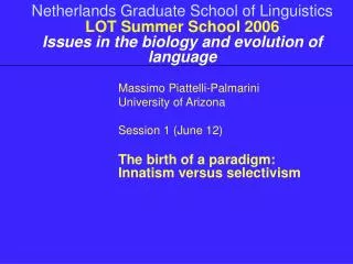
Angular Dependence Goal: to show the different angular dependence of FBGs for plane and cylindrical waves • Plane wave: • Cylindrical wave: For θ=0 (PZT-FBG angle) the principal strains are in the x,y directions: Analytical angular dependence for plane wave assumption (cos2(β), green line) and cylindrical assumption (blue line) at 21mm from the source
Angular Dependence Cylindrical wave (cont.): When ignoring the tangential effect, the error could be large. For example, at β=75 degrees: 75 degrees comparison of general analytic strain (blue) measured signal (green) and analytic without tangential strain (red) Conclusion: The tangential strain affects the angular dependence and cannot be ignored at small distances from the source.
Rosette Calculations • Rosettes are used for damage location in NDT • Prior work uses only plane wave rosettes • Our work intends to: • Enable accurate location of damages in a close range • Present different calculation for each wave (planar/ cylindrical) What is a rosette?
Rosette Calculations • For a Plane wave: • Only 2 FBGs are required! • Signals are in-phase. • Max. values can be used Signals of 2 FBGs oriented at different angles in the plane wave case
Rosette Calculations • For a cylindrical wave: • 3 FBGs are required! • Signals are not necessarily in phase and differ from each other!!! • Signal values should be taken at a specific time! Measured strains for angles: 0 (blue), 45 (green) and 90 (red) degrees
Rosette Calculations • Cylindrical wave (cont.) Angle to the source: • Analytically (θ is 0). Estimated angle to the source (bold blue line), using analytical strain solutions (also added for time reference)
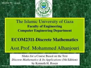
Rosette Calculations • Cylindrical wave (cont.) Angle to the source: • Angle from measured signal was not as expected!!! • Applying a 1mm shift to one of the FBGs in the analytical calculation shows a similar effect ☺ Estimated angle to the source (bold blue line), using measured strain signals (also added for time reference) The effect of 8*10-7 [sec] time shift (~1 mm) of one of the analytical strain solutions on the angle estimation capability
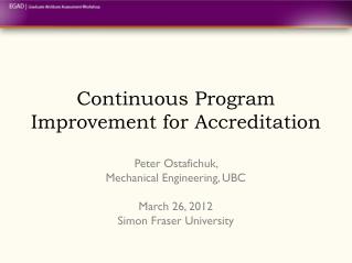
Rosette Calculations • Conclusions and Implications • Realistically, the estimated angle will never be constant • Improved analysis method for cylindrical rosettes: • Perform analysis for each time step • Choose the angle for which the denominator is maximal • In plane wave rosettes this problem does not exist since it is possible to assume signals are in phase • Golden Rule: For long distance use plane wave rosette, For short distance- cylindrical wave rosette Estimated angle to the source (bold blue line), using measured strain signals (also added for time reference)
Summary of Findings • Exact analytical solutions for a pulse of plane and cylindrical Lamb waves was calculated. • Parameters for a Finite Element Model were determined. • The angular dependence of FBGs at close range to the transducer, where the wave is cylindrical, was analyzed and measured. • Three FBG rosette calculations were performed and the effect of the tangential strain on the angle finding was analyzed. • The effect of co-location error was demonstrated.
Future Work • Applying FBGs to NDT system for damage detection • Real time monitoring • High accuracy at all distances • Anisotropy • Composite plates, which are common in the industry, are usually anisotropic • Ability to embed optical fibers • Phase and group velocities are angle dependent
Acknowledgements • Prof. Moshe Tur • Lab colleagues, and especially: • Yakov Botsev • Dr. Nahum Gorbatov • Iddo Kressel • Shoham