Download
1 / 18
590 likes | 1.69k Views
BASIC RADIATIVE TRANSFER. RADIATION & BLACKBODIES. Radiation Flux (F) [W/m 2 ] Intensity (I) [W/m 2 /sr] Monochromatic Intensity (I l ) [W/m 2 /sr/nm]. Objects that absorb 100% of incoming radiation are called blackbodies

E N D
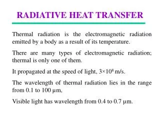
RADIATION & BLACKBODIES Radiation Flux (F) [W/m2] Intensity (I) [W/m2/sr] Monochromatic Intensity (Il) [W/m2/sr/nm] Objects that absorb 100% of incoming radiation are called blackbodies For blackbodies, emission (Bl) is given by the Planck function: Function of T only! Bl lmax = hc/5kTWien’s law lmax Emittance: 1 < el< 0 for grey bodies (el=1 for blackbodies) Kirchoff’s Law: absorptance = emittance
RADIATIVE TRANSFER EQUATION I A B C D C: Scattering Out A: Absorptance (Beer-Lambert Law) D: Scattering In complex because of scattering from all directions, can be approximated as: B: Emission (Kirchoff’s Law)
RADIATIVE TRANSFER EQUATION II Absorption and emission (depends on incident intensity and T of layer) Scattering (increase in outgoing if <I’l> > Il) Extinction coefficient: Slant versus Vertical Radiation: d = optical depth dl= total column optical depth
EXTINCTION = SCATTERING + ABSORPTION Scattering from milk, ink, and water on an overhead projector Transmission through milk, ink, and water projected onto a screen
RADIATIVE TRANSFER EQUATION III =1-w Single scattering albedo: w Simplification #1: No Scattering (valid for IR with no clouds) Schwarzchild’s Equation: Can be solved explicitly (first order, linear ODE) Simplification #2: No Emission(valid for the UV/visible/near-IR) Requires an understanding of scattering properties to solve
IN PRACTICE, THERE ARE MANY CONTRIBUTIONS TO ATMOSPHERIC RADIATION… Atmosphere Emission from molecules Transmission through a cloud Absorption Scattering from a cloud Emission from a cloud Scattering Cloud Aerosol / Molecules Scattering within a cloud Scattering / reflection oh a cloud Transmission through a cloud Emission from the surface Absorption on the ground Scattering / Reflection on the ground Adapted from Andreas Richter
INTERACTION OF RADIATION WITH GASES Also in UV/vis: Ionization-dissociation Characterized by discrete spectral lines Characterized by absorption cross section
SPECTRA OF ATMOSPHERIC GASES HAVE FINITE WIDTHS Pressure (Lorentz) broadening can obscure individual lines Petty, 2004
EXAMPLES OF ABSORPTION SPECTRA UV Andreas Richter Transmittance IR 15 mm 3.6 mm [Clerbaux et al., ACPD, 2009]
SCATTERING If a photon is absorbed and then immediately re-emitted this is called scattering. It depends on particle shape, size, index of refraction, wavelength of incident radiation and the viewing geometry. Usually, scattered photons have the same wavelength (elastic scattering) but not the same direction as the original photon. Scattering regime can be assessed using the Mie parameter: = 2 r / Mie-Scattering (0.1 < a < 50) Geometric (optics) scattering (a > 50) Rayleigh Scattering (a < 0.1) The phase function P() gives the distribution of scattered intensity as a function of scattering angle; the integral over all wavelengths is 1. [Petty, 2004]
Reflectivity and Emissivity of Various Surface Types There can be little relationship between reflectivity at visible and infrared wavelengths! Petty, 2004
POLAR ORBIT • Most composition measurements thus far have been from low-elevation (LEO), sun-synchronous orbits. • Sun-synchronous: satellite precesses at same rate as Earth revolves around • Sun (~1°/day) • satellite crosses equator at same local time each day • Pros: • Global coverage • High signal • Cons: • Poor coverage (temporal, clouds) • Shorter instrument lifetime
EXAMPLE OF TERRA ORBIT Local Time = GMT +longitude/15 GMT Terra is daytime descending orbit When converted to local time, can see the same equator cross over ~10:30 & 22:30
SOLAR OCCULTATION ORBIT SCISAT-1 Orbit • Pros: • Very good signal (new species!) • Good vertical resolution • No surface term to characterize • Cons: • Poor coverage (~30 obs per day) • Lower troposphere not observed
GEOSTATIONARY ORBIT Geostationary orbits (GEO) match the period of satellite rotation with the Earth’s rotation (altitude ~ 35,800 km), fixed over the equator (view up to 60°) • Pros: • constant observation (diurnal profiles, cloud contamination less detrimental) • Longer instrument lifetime (less drag) • Cons: • reduced signal • worse spatial resolution limit of spatial resolution possible ~ 1km
GEOSTATIONARY NETWORK OF THE FUTURE? GEO-CAPE NASA: 2016? Sentinel-4/5 ESA: 2017 GEO-Asia JAXA: 2017? All three likely to include composition measurements in both UV & IR