Download
1 / 25
250 likes | 397 Views
Seminar on “UNIFIED MODELLING LANGUAGE” SUBMITTED TO: SUBMITTED BY: ER.ANSHU PRASHAR ANJANI (1706204) RAKESH (1706201). CONTENTS. Definition Modeling Diagrams Overview Structure Diagram Class Diagram Component Diagram Deployment Diagram Composite Structure Diagram

E N D
Seminar on “UNIFIED MODELLING LANGUAGE” SUBMITTED TO: SUBMITTED BY: ER.ANSHU PRASHAR ANJANI (1706204) RAKESH (1706201)
CONTENTS • Definition • Modeling • Diagrams Overview • Structure Diagram • Class Diagram • Component Diagram • Deployment Diagram • Composite Structure Diagram • Behaviour Diagram • Activity Diagram • State Machine Diagram • Use-Case Diagram • Interaction Diagram • Communication Diagram • Sequence Diagram • Meta-Modeling • Criticisms
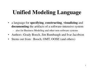
DEFINITION • Unified Modeling Language (UML) is a standardized general-purpose modeling language in the field of software engineering. UML includes a set of graphical notation techniques to create visual models of software-intensive systems. • It is used to specify, visualize, modify, construct and document the artifacts of an object-oriented software intensive system under development.UML offers a standard way to visualize a system's architectural blueprints. • UML combines best techniques from data modeling, business modeling,object modeling, and component modeling. It can be used with all processes, throughout the software development life cycle. • UML has synthesized the notations of the Booch method, the Object-modeling technique and Object-oriented software engineering by fusing them into a single, common and widely usable modeling language. • UML is a de facto industrystandard, and is evolving under the auspices of the Object Management Group (OMG).
MODELING UML diagrams represent two different views of a system model: • Static (or structural) view: Emphasizes the static structure of the system using objects, attributes, operations and relationships. It includes class diagrams and composite structure diagrams. • Dynamic (or behavioral) view: Emphasizes the dynamic behavior of the system by showing collaborations among objects and changes to the internal states of objects. This view includes sequence diagrams, activity diagrams and state machine diagrams.
CLASS DIAGRAM • A class is depicted here.
COMPONENT DIAGRAM Purpose-to show the dependencies that the software has on the other software components in the system.
DEPLOYMENT DIAGRAM • Purpose-to show where the different components of the system will physically run and how they will communicate with each other. • Notations Used: • Node-3D cube with name of the node at the top of the cube. • Name of node-[instance name] : [instance type]
COMPOSITE STR.DIAGRAM • It includes: • Parts • Ports • Connectors
MORE STRUCTURAL DIAGRAMS • Object diagram: shows a complete or partial view of the structure of a modeled system at a specific time. • Package diagram: depicts how a system is split up into logical groupings by showing the dependencies among these groupings.
ACTIVITY DIAGRAM • Shows procedural flow of control between two or more class objects while processing an activity. • Notations Used: • Solid circle • Rectangle with round corners • Transition lines • Termination point
STATE MACHINE DIAGRAM • Models the different states that a class can be in and how that class transitions from state to state. • Notations Used: • Initial Starting Point • Transition Lines • Rectangle with round corners • Decision Point • Termination Point
USE CASE DIAGRAM • Purpose: to help development teams visualize the functional requirements of a system. • Notations Used: • Oval • Stick Person • Relationship Lines
SEQUENCE DIAGRAM • 2 dimensions. • Notations Used: • Box at the top • Open arrowhead Line • Dotted line
META MODELLING • Architecture to define UML • Developed by Object Management Group • 4-layer architecture
CRITICISMS • Language bloat- The language is unnecessarily large. • Problems in learning and adopting- Engineers lacking the prerequisite skills face problems in learning UML. • Cumulative Implementation-UML is able to represent some systems more concisely or efficiently than others. Thus a developer gravitates toward solutions that reside at the intersection of the capabilities of UML and the implementation language. • Dysfunctional interchange format-While the XMI standard has been largely ineffective in the practical interchange of UML 2.x models due to two reasons. Firstly, XMI 2.x is large and complex in nature. Secondly, the UML 2.x Diagram Interchange specification lacks sufficient detail to facilitate reliable interchange of UML 2.x notations between modeling tools.