Download
1 / 20
200 likes | 314 Views
LHC Injection and transfer lines. Malika Meddahi, Brennan Goddard, Verena Kain, J ö rg Wenninger On behalf of all contributors In particular: K.Fuchsberger, S.Fartoukh, V.Mertens, J.Uythoven, M.Barnes,

E N D
LHC Injection and transfer lines Malika Meddahi, Brennan Goddard, Verena Kain, Jörg Wenninger On behalf of all contributors In particular: K.Fuchsberger, S.Fartoukh, V.Mertens, J.Uythoven, M.Barnes, E. Carlier, W.Bartmann, C.Hessler, L.Jensen, R.Jones, M.Lamont, R.Giachino, G.Mueller, S.Redaelli, W.Herr, F.Schmidt, OP crews on shift…
Scope • LHC transfer lines – 2009 optics studies • Trajectory • Dispersion • Kick response • Aperture • Injection regions • Injection steering • MKI wave form • Injection protection • Injection aperture • List of subjects to follow-up
1- LHC Transfer line Main outcomes from all transfer line beam time measurements – trajectory, kick response and dispersion measurements: • Transfer line BPMs: • calibration performed and included in the measurements -Rhodri, Lars and team • + essential data from kick response measurements (Kajetan) • request for additional BPMs upstream of TT60 – hidden trajectory bump – • available for 2011 start-up • more robust dispersion measurements in TI 8 thanks to the dual plane reading • and the additional BPMs in the LHC injection area • in TI 2, same improvements will be available for the 2011 start-up– BI teams
Trajectory examples TI 8 bare trajectory TI 8 corrected trajectory -few correctors, <20 mrad
Transfer line magnetic model: • TT60 MBE CC switched to MBB – vertical bare trajectory as expected • MQIs DK/K = ~1.006 • MQI measurements by magnet group • MBI sext. component of ~ -4.5e-4 @ r=25mm (idea from S.Fartoukh) • Confirmed by magnet group from 2D calculations • MBI quad. component of ~1.35e-4 @ r=25mm • Feed-down from systematic horizontal offset in MBI Nominal Idem + Dk/k+b2+b3 Idem + initial cdts Rematched optics with b2,b3 components and use new MQI CC
Kick response measurements – TI 8 - V plane – Before rematching ~ 0.7% over-focussing in vertical plane apparent cf model Courtesy: Kajetan Kick response measurements – TI 8 - V plane – After rematching
Dx TI 8 1st and 2nd order dispersion with rematched optics D’x
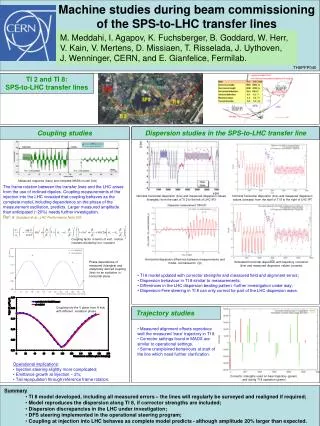
TI 2 and TI 8 aperture studies • - Momentum aperture: +/- 0.35 to 0.4%, as expected. • - Physical aperture explored in both lines in H and V, at different phases, 30 deg intervals, using on-line model and dedicated knobs
In both planes in both lines: • No bottlenecks • Note: aperture restriction between • P8 MSI and Q5 solved after • re-alignments - Measured aperture ≥10 nominal s Few phases in TI 2 to complete
2- Injection region Much injection checks and setting-up work performed through the LHC beam commissioning • Injection steering • Injection region aperture • Kick response – dispersion measurements • MKI waveform • TDI and TCLIA/B setting up around orbit, LHCb BeamCdtMonitor, setup of TDIs to golden orbit – see Wolfgang’s talk • Checked losses on TDI & IR8 for MKI off/over-injecting – see Christos’ talk • Tests of injection and matching with xing/sep bumps on – see Werner’s talk • Injection kicker timing in • Injection of multiple bunches • …
TI 2-TI 8 Steering • TI 2+S23 and TI 8+S78 selections of the steering display now by default: • TL trajectory • Ring First turn - Closed orbit = injection oscillation • Closed orbit is estimated from average of 50 first turns • >> ensures that TL steering always brings beam onto the CO Trajectory FT-CO 11
Injection Autopilot • Feedback tools inside steering program to correct injection oscillations: • Same tool used for SPS injection oscillations & SPS target steering. • Manually activated. • Algorithm can be configured (DB). Presently: • Fit a betatron oscillation to the ring FT-CO • (in H subtract dp/p error). • Interpolate fit to a virtual start point (pos + angle). • If pos/angle out of tolerance, correct • with 2 correctors at end of line. • >> tested & works well ! • May need to tune algorithm because of TL collimation. • Global MICADO (towards ref) better? • >> need more experience ! 12
Kick response measurements -1 Data in very good agreement with model. All measurements were done at deltap/p = - 0.5 permil. Figures show a comparison between measurements (blue) and model (red). Beam from left. H plane V plane Courtesy Kajetan
Kick response measurements -2 H+V response of horizontal kicker MCIAH.80204 for TI8 and LHC sector 78. H+V response for vertical kicker MCIAV.80704 for TI8 and LHC sector 78. Vertical (blue background) couples to horizontal (red background) Courtesy Kajetan
Point 2 / 8 TDI and TCLIA/B setting up • Transfer line protection devices: setting up partially done • TDI / TCDI : done • See Wolfgang Bartmann presentation
MKI 2 and 8 waveform measured Looks OK except for 2% overshoot, both MKI2 and 8 – being corrected Courtesy M.Barnes
Injection kicker timing in • Both beams timed in • Adjusted with OASIS signals • Configured for abort gap keeper • Checked beam injected OK with acceptable oscillations • Need to check the fine timing to fit full SPS batch Beam2 Beam1
Multiple bunch injection (and fixes) • 4 bunch injection sequences worked after timing in MKI and MKD • Need to be aware that injecting near to abort gap needs consideration • bunch is always at the head of the injection kicker pulse – always 11 ms gap as result after last bunch • may need to reorder some injection sequences, especially with ‘trailing pilot’ • may need to change order of injection for some bunches. • Setting up of protection devices to (re)do for high intensity
3- List of subjects to follow-up • Transfer lines: Importance of: • Regular survey checks and re-alignment • Steering with minimum corrector number and strength • Accurate characterisation of the main magnets • Noise on QPS from TF pulsing? Worry about other EMC sources around ring? • Injection region: • FT-CO evaluation is presently based on FIFO acquisition: • Works only when injecting into EMPTY ring. • To be able to work on ANY injection (also with circ. beam): • FT-CO from capture data. Code written – needs testing. • Capture data must be automatically configured and enabled to trigger on the buckets corresponding to the injected bunches (>> injection sequencer). • ‘Interference’ with PC interlocks of TLs: • Corrector interlock margin presently +- 10 mrad (from CNGS experience). • Must find a compromise between protection (small tol.) and steering flexibility (larger tol.). Note that shift crews have the right to change the corrector reference settings (not the tolerance).
Injection region (cont’d): • Still investigate how to over-inject without interlocking • Puzzle of losses in P8 on MQX – issue of BLM range • Fine synchronisation of injection kicker pulse to bucket 1 • Setting up of TCDIs and TCLIA/Bs • Losses on TCDQ/TCSG for B1 at injection– (more) checks to make • BQM information for IQC – to be made operational • Injection sequences to revisit with ‘trailing pilot’ • May need to change order of injection for some bunches. • Need adequate (re)commissioning time