Download
1 / 58
720 likes | 1.36k Views
Connection Details for Prefabricated Bridge Elements and Systems. Michael P. Culmo , P.E. Vice President of Transportation and Structures CME Associates, Inc., East Hartford, CT. Learning Outcomes. After completing this Module, you will be able to:

E N D
Connection Details for Prefabricated Bridge Elements and Systems Michael P. Culmo, P.E. Vice President of Transportation and Structures CME Associates, Inc., East Hartford, CT
Learning Outcomes After completing this Module, you will be able to: • identify roadblocks to accelerated bridge construction • identify the resources for locating Connection Details for PBES • describe features of PBES that improve the quality of the finished product • recognize a typical construction schedule for a bridge built with PBES • recall ways to save money by using ABC and PBES
Roadblocks to Accelerated Construction The primary concerns that owner agencies have with respect to adopting accelerated construction techniques are: • Need for Quality Details • Durability • Design Methodologies and Training • Construction Methodologies
“Connections Details for Prefabricated Bridge Elements and Systems” • FHWA has developed this manual • This publication is intended to provide information that will go a long way to answering all four of the previous concerns. • Focus on details that have been used in the past.
“Connections Details for Prefabricated Bridge Elements and Systems”Project Goals: • Gather details of Connections that have been used on accelerated bridge construction projects • Investigate transfer of technology from other markets into the bridge market • Parking Garages • Stadiums • Buildings
“Connections Details for Prefabricated Bridge Elements and Systems” All details need to pass a critical test before being published in the document: • Does the connection result in a rapid construction process? • Does the connection transmit the forces between elements effectively? • Is the connection durable? • Is it cost effective and easy to construct? • If a process or connection is proprietary, is there more than one supplier?
Sources of Data • State DOT’s • Questionnaires sent via e-mail • Federal Agencies • Researchers (previous and current) • Producers/Fabricators
Total Bridge Element Prefabrication Everything shown can be prefabricated
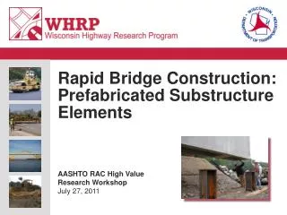
Complete Bridge Element Prefabrication New Hampshire Project • How fast can we build a bridge? • Experimental project • All components prefabricated • 115 foot span • Precast cantilever abutments • Clock started after old bridge was removed • Roadway open to traffic in 8 days • Time Lapse Video on YoutubeTM • Search “Epping Bridge Construction”
Manual Distribution • Availability • Published June 2009 • Is available through FHWA Highways for LIFE website www.fhwa.dot.gov/hfl/
Other Sources for Details • Utah DOT ABC Website • www.udot.utah.gov (search ABC) • Piers, abutments, walls, decks • PCI Northeast • www.pcine.org (Bridge resources) • MassDOT • Working on new ABC manual • NCHRP Report 681 • Development of a Precast Bent Cap System for Seismic Regions • Web search “NCHRP Report 681”
Case Scenario • 4 lane bridge over an expressway • Existing bridge has deteriorated beyond repair • Heavy traffic on both roadways • A temporary bridge or staged construction is an option • The local business will accept a short term closure with the detour • As opposed to a long term staged project • Establish the detour and accelerate the bridge construction to less than 30 days
Existing bridge issues Leaking Deck Joints Low Clearance Salt spray attack from vehicles Salt spray attack from vehicles
Proposed Bridge Type After a formal study, the owner opted for the following structure criteria: • Continuous steel girders (weathering steel) • Reduce to a two span bridge • Increase clearance by raising approach grades (3’) • Use integral abutments (no deck joints) • Composite concrete deck • Membrane waterproofing and Bituminous wearing surface • Open steel railings (galvanized)
Proposed Bridge No Deck joints Move substructures away from roadway Increase vertical clearance Build new piers and abutments in new locations
Sources of details - FHWA Connections manual: “Connection Details for Prefabricated Bridge Elements and Systems” • Review Chapter 1 • Investigate connection types, materials, tolerances • Search applicable sections of other chapters for details - NCHRP Report 681 “Development of a Precast Bent Cap System for Seismic Regions” - Utah DOT ABC Standards
Connection Types Chosen • The owner chose the following connection types • Grouted reinforcing splice couplers • Quick, proven system • Can develop full bar strength • Simplifies the design process (same as CIP) • Grouted PT Ducts • Provides significant adjustability at cap connection • Grouted Voids • Corrugated metal pipe voids for integral abutments • Small blockouts for pinned connections (approach slabs) • Concrete Closure pours between precast elements • Use for a limited number of connections (slower)
Grouted Reinforcing Splice Couplers • Emulates a reinforcing steel lap splice • Multiple companies – non-proprietary • Used in precast parking garages, stadiums and bridges • Installation video on youtube • Search “Georgia Pier Construction”
NCHRP Report 681 Detail Grouted PT Duct • Similar to grouted sleeves • Used in several states • Tested for high seismic regions • Significant adjustability • Details, specifications and design information available
Footing to Footing Connection Use CIP Closure Pour • Cast closure pour during structure erection • Design precast for structure DL • Design continuous footing for total loads
Column to Cap Connection Use details from NCHRP Report 681
Completed Pier Column to footing connection Column to cap connection Footing to footing connection Footing to subgrade connection
Abutment Details • Integral Abutment to piles • Section 3.2.3.1 Precast Integral Abutment to Piles • Corrugated metal pipe voids • Place over pile and fill with concrete • Detail developed by Iowa DOT • Used in other states also • Reduces element weight • Has large capacity to transfer pile loads • Shear transfer via shear friction
Abutment Cap to Cap Connection • Use Utah DOT Details • Concreted key • Use integral diaphragm to link caps together
Completed Abutment Approach slab connection Capto cap connection Pile to cap connection
Superstructure to Abutment Connection Use CIP Closure Pour • Utah DOT Detail • Allows for significant adjustability • Provides connection between abutment stem elements
Completed Superstructure Longitudinal crown connection Connection to beam CIP Curb Transverse slab connection Longitudinal PT Integral Abutment Connection
Complete Bridge Membrane waterproofing with bit. Wearing surface Precast full depth composite deck Precast Integral Abutment Precast Pier