Download
1 / 43
430 likes | 521 Views
Progress in Barrier Stacking. W. Chou, J.Griffin, K.Y. Ng, D. Wildman Fermilab Presented to MAP Meeting IUCF, Indiana March 12-13, 2007. Content of Talk. Motivation Method Simulation Experiment. Fermilab Accelerator Complex. Booster – the Bottleneck.

E N D
Progress in Barrier Stacking W. Chou, J.Griffin, K.Y. Ng, D. Wildman Fermilab Presented to MAP Meeting IUCF, Indiana March 12-13, 2007 March 12-13, 2007
Content of Talk • Motivation • Method • Simulation • Experiment March 12-13, 2007
Fermilab Accelerator Complex March 12-13, 2007
Booster – the Bottleneck • The Booster is a 30 years old machine has never been upgraded. • The 400-MeV Linac can deliver 25 x 1012 particles perBooster cycle. • The 120-GeV Main Injector can accept 25 x 1012 particlesper Booster cycle. • However, the 8-GeV Booster can only deliver 5 x 10¹²particles per cycle. March 12-13, 2007
Solution— Stacking • A solution is to stack two Booster bunches into one Main Injector RF bucket. • This is possible because the much larger momentum acceptance of the Main Injector. (bucket width = 18.9 ns) March 12-13, 2007
Stacking Goal • Goal for Run II – To increase protons per second (pps)on the pbar target by 50% • Baseline: 5 x 10¹² every 1.467 sec • Goal: 2 x 5 x 1012 every 2 sec • Goal for NuMi – To increase pps on NuMi target by 60% • Baseline: 3 x 10¹³ every 1.867 sec • Goal: 2 x 3 x 1013 every 2.333 sec • Slip stacking can raise proton intensity from 5.0 x 10¹² per batch to 7.0 x 10¹². (K. Seiya, et al., PAC’05) • We are going to study barrier stacking here. March 12-13, 2007
Barrier Stacking by J. Griffin Booster batch injected off-energy so that top of batch slips 42 bkts per booster cycle. Barrier moves to left at 42 bkts per booster cycle. After 1 booster cycle, first batch passes front of barrier. 2nd batch is injected 42 bkts from 1st batch. Strength of barrier is determined by δf1 = δf2. This is the only parameter in the model. No solution if energy spread is too large. March 12-13, 2007
For the injection of Booster batch into MI, allowablemaximum energy spread is ΔE = ±4.90 MeV.Corr. integrated barrier strength VT1 = 3.142 kV-µs. • Booster bunch area: ~0.10 eV-s, bucket width: 18.9 ns. • If completely debunched,ΔE = ±2.64 MeV. • For the bunch filling whole bucket,. ΔE = ±4.15 MeV • If a harmonic cavity is installed, booster bunch can be lengthened with ΔE reduced. • E.g., bunch at Vrf = 5.0 kV and a 3rd harmonic cavity reduces ΔE to ±5.18 MeV. • E.g., bunch at Vrf = 4.8 kV and a 2nd harmonic cavity reduces ΔE to ±4.56 MeV. • If ΔE can’t be reduced, method still works if barrier is allowed to move faster. However, this will reduce the number of batches to be injected. March 12-13, 2007
Simulation of Stacked Injection 1st batch injection 2nd batch injection March 12-13, 2007
3rd batch injection 4th batch injection March 12-13, 2007
5th batch injection 6th batch injection March 12-13, 2007
7th batch injection 8th batch injection March 12-13, 2007
9th batch injection 10th batch injection March 12-13, 2007
11th batch injection 12th batch injection March 12-13, 2007
Best time to re-capture After 12th Booster cycle After 13th Booster cycle March 12-13, 2007
Hardwares • Task: To build two ±8 kV wideband RF cavities. (i.e., the barrier RF) • There is no low-level RF. The on-and-off of the RF voltage is handled by a high voltage solid-state fast switches made by Behlke Co. (German). • These fast switches have been applied to the design of an RF chopper built at Chiba by a KEK-Fermilab team. W. Chou, et al., Design and Measurements of a Pulsed Beam Transformer as a Chopper, KEK Report 98-10 (Sep. 1998). March 12-13, 2007
Finemet Cavity as a Chopper(installed on the linac of HIMAC in Chiba) March 12-13, 2007
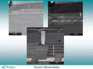
Finemet Core(a nanocrystal magnetic alloy patented by Hitachi) March 12-13, 2007
High-Voltage Fast Switch(MOSFET Switches made by Behlke Co.) March 12-13, 2007
The Broad-Band Barrier RF Cavity W.Chou, et al., Barrier RF System and Application in MI, PAC’05 March 12-13, 2007
Building of the Barrier RF System Switch March 12-13, 2007
Building the Barrier RF Cavity March 12-13, 2007
Testing a RF Cavity One barrier Two barriers per MI period March 12-13, 2007
Barrier Stacking Experiment Normal Inj. from Booster to MI at frf = 52,811,400 Hz. Injection is on-energy. No drift at all. Barrier is off. 2nd batch injected 84 bkts from first batch. Mountain-view is 256 MI turns per trace. March 12-13, 2007
Off-Energy Injection with Barrier Off • Inject at frf = 52,812,014 Hz (614 Hz > nominal). • Booster above transition, so beam energy < nominal. • 2nd batch injected 42 bkts from the first. March 12-13, 2007
Computation of ΔE offset • (Δfrf/frf)B = 1.163x10⁻⁵ • Booster slip factor ηB= 0.022436 • Mom offset Δp/p = -ηB-1(Δfrf/frf)B= 5.136x10⁻⁴ • Energy offset ΔE = -4.54 MeV • However, once inside MI, which is at ηMI= -0.008888,beam revolves at a lower frequency than nominal: March 12-13, 2007
clock frf = 52,812,014 Hz 11.56 MeV frf = 52,811,400 Hz normal 4.54 MeV beam Because there is no low-level RF, the barrier and the mountain-view will be at the locked RF frequency. The movement of the barrier can be accomplished by adding a delay. March 12-13, 2007
Turning on Barrier on the Right Side The beam is seen reflected from barrier on the right. March 12-13, 2007
Adjusting Barrier Position and Speed Barrier trigger = Mountain view = 52,812,014 Hz Stationary barrier One barrier moving March 12-13, 2007
Moving Barrier, 4 Pulses, No Bunch Rotation Mountain view = 52,812,014 Hz, frf = 52,812,014 Hz Consecutive batch spacing 42 buckets Final beam width of 4 pulses only ~3.5 μs, half of that w/o barrier 3.5 μs (unstacked 4 batches: 6.36 μs) March 12-13, 2007
Moving Barrier, 6 Pulses, No Bunch Rotation Mountain view = 52,812,014 Hz, frf = 52,812,014 Hz Consecutive batch spacing 42 buckets Final beam width of 6 pulses only ~5.5 μs, half of that w/o barrier 5.5 μm Some reflected beam catches up with moving barrier. (unstacked 6 batches: 9.54 μs) March 12-13, 2007
Moving Barrier, 6 Pulses, with Bunch Rotation Mountain view = 52,812,014 Hz, frf = 52,812,014 Hz Consecutive batch spacing 42 buckets Final beam width of 6 pulses only ~5.5 μs, half of that w/o barrier 5.5 μs Some reflected beam catches up with moving barrier. (unstacked 6 batches: 9.54 μs) March 12-13, 2007
Moving Barrier, 8 Pulses, No Bunch Rotation Mountain view = 52,812,014 Hz, frf = 52,812,014 Hz Consecutive batch spacing 42 buckets (The 8 injections were lousy but no time to improve it) March 12-13, 2007
Recapture (no bunch rotation) Mountain view = 52,812,016 Hz, frf = 52,812,016 Hz 2nd batch 42 bkts from 1st injection Capture Vrf = 850 kV in ~45 ms March 12-13, 2007
First Few Turns of the First Batch Mountain view = 52,812,016 Hz, frf = 52,812,016 Hz No bunch rotation March 12-13, 2007
First Few Turns of the First Batch Mountain view = 52,812,016 Hz, frf = 52,812,016 Hz With bunch rotation, B:BRLVL = +8.7 Not as dramatic as expected. Capture result almost the same. March 12-13, 2007
V Beam’s Energy Spread barrier frf = 52,812,014 Hz clock T1 11.59 MeV frf = 52,811,400 Hz normal ΔEtotal 4.55 MeV beam beam ΔE • Barrier width is fixed at T1 = 0.3 μs, height is reduced gradually from V = 12 kV until beam leaks out. • is confined, • from which beam’s energy spread ΔE can be inferred. March 12-13, 2007
With BR, 9.5 kV —> ΔE = 6.42 MeV With BR, 9.0 kV —> ΔE = 5.77 MeV • Thus half energy spread is 5.77 MeV < ΔE ≤ 6.42 MeV • But with BR off, need 11 kV to avoid leakage, ΔE ≤ 8.14 MeV. • Thus bunch rotation works, although not dramatically. March 12-13, 2007
With BR, 6-turns 16 kV —> ΔE > 13.15 MeV With BR, 2-turns injection 11 kV —> ΔE > 8.14 MeV It is hard to imagine ΔE > 13.15 MeV for 6-turn beam. We are told that it should be from 8 to 12 MeV. March 12-13, 2007
Re-capture Results • Bunch area increases 8.15-fold. • Amount of charge captured proportional to Height x Width, or 0.156/0.128/2 = 61%. March 12-13, 2007
Recapture Vrf= 850 kV, frf= 52,811,400 Hz bunch rotation (yes or no?), 6 Booster turns • Large beam loss. Maybe ΔE is much larger and cannotpenetrate the moving barrier. • Beam passes through reflecting barrier on the right; strength of that barrier is not large enough. March 12-13, 2007
Moving barrier: 6 kV, 0.3 µs, integrated strength 1.8 kV-µs. • Barrier is not strong enough to accel. top of beam to +ve energy. • Final energy spread is large —> beam loss in recapture. • At this moving rate, barrier V can increase up to V = 8.69 kV. • Then final half spread is ΔE = 15.0 MeV. • This can be further reduced by increasing V and let barrier move faster. 17.5 MeV frf = 52,812,014 Hz clock 0.15 MeV 11.6 MeV frf = 52,811,400 Hz nominal 17.5 MeV 4.6 MeV beam beam 6.4 MeV March 12-13, 2007
Summary • We have been successful in • injecting into MI off-energy, • setting a barrier moving at a prescribed rate, • stacking so far up to 8 booster batches into a width of ~ 4 batches, • re-capturing the stacked beam, although with large increase in bunch area and large beam loss. • Future improvement: • Better understanding of the beam and RF maneuvering. • Improvement in bunch rotation in Booster so as to reduce ΔE, which is the source of beam loss in recapturing. • To built a low-level RF, if possible, so that barrier and mountain view can be referenced to MI nominal frequency. • Study with more intense beam and more batches. March 12-13, 2007