Download
1 / 34
410 likes | 988 Views
System Level Analysis of Fast, Per-Core DVFS Using On-Chip Switching Regulators. Wonyoung Kim, Meeta Gupta Prof. Gu-Yeon Wei, Prof. David Brooks Harvard University School of Engineering and Applied Sciences. Slow Voltage Scaling with Off-Chip Regulator. 870mV. 53.2us.

E N D
System Level Analysis of Fast, Per-Core DVFS Using On-Chip Switching Regulators Wonyoung Kim, Meeta Gupta Prof. Gu-Yeon Wei, Prof. David Brooks Harvard UniversitySchool of Engineering and Applied Sciences
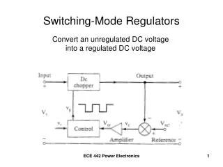
Slow Voltage Scaling with Off-Chip Regulator 870mV 53.2us L.T. Clark et al, “An Embedded 32-b Microprocessor Core for Low-Power and High-Performance Applications”, JSSC 2001 Conventional DVFS with off-chip regulator Voltage Transition: 16mV/us
Fast Voltage Scaling with On-Chip Regulator Fast DVFS with proposed on-chip regulator Voltage Transition: 10mV/ns
Form Factor of Off-Chip Regulators http://www.tomshardware.comGigabyte GA-P35C-DS3R Difficult to place multiple regulators on board
Contents • Potential of Fast, Per-Core DVFS • Switching Regulator Background • Overheads of On-Chip Regulators • Overall Energy Consumption • Conclusions
Architectural Simulation Framework • 4-core in-order processor • 1GHz @ 1V • Maximum power: 1.6W • Benchmarks: cholesky, fft, facerec, raytrace, ocean • mcf (memory bound), applu (cpu bound) • Simulator: SESC a multi-core simulator with power models based on Wattch, Cacti, and Orion. • Four Voltage/Frequency Levels for DVFS • (1V/1GHz, 0.866V/866MHz,0.733V/733MHz, 0.6V/600MHz) • Offline DVFS algorithm (linear programming)
10% static10us1us200ns100ns static10us1us200ns100ns 30% Slow vs. Fast DVFS mcf fft • More savings with finer DVFS intervals • Savings differ among different benchmarks
raytracecholeskyfacerecfftocean 15% Chip-Wide vs. Per-Core DVFS Chip-wide DVFS (100ns) Per-core DVFS (100ns) • More savings with using per-core DVFS • Savings differ among different benchmarks
raytracecholeskyfacerecfftocean Chip-Wide vs. Per-Core DVFS Chip-wide DVFS (100ns) Per-core DVFS (100ns) • More savings with using per-core DVFS • Savings differ among different benchmarks
Chip-Wide vs. Per-Core DVFS Chip-wide DVFS (100ns) Per-core DVFS (100ns) 4 cpu3 mem, 1 cpu2 mem, 2 cpu1 mem, 3 cpu4 mem • Energy saving with per-core DVFS depends on the heterogeneity of workloads in each core.
20% Chip-Wide vs. Per-Core DVFS Chip-wide DVFS (100ns) Per-core DVFS (100ns) 4 cpu3 mem, 1 cpu2 mem, 2 cpu1 mem, 3 cpu4 mem • Energy saving with per-core DVFS depends on the heterogeneity of workloads in each core.
Contents • Potential of Fast, Per-Core DVFS • Switching Regulator Background • Overheads of On-Chip Regulators • Overall Energy Consumption • Conclusions
Switching Regulator Design Inductor Current Processor Cout
Switching Regulator Design Inductor Current Processor Cout
Switching Regulator Design Inductor Current I2R Processor Cout CV2
On-chipdecap Multi-Phase Regulator Design LoadCurrent • Advantages • Interleaved inductor currents smaller ripple • Replace filter capacitor (Cout) with on-chip decap • Examples • Hazucha et al JSSC 2005 • Wibben et al VLSI 2007, Abedinpour et al ISSCC 2006
Simulation Framework • Assume regulator built in 65nm process • Regulator model built with Simulink/Matlab • Process parameters extracted using Cadence simulations • 1V output voltage with +- 10% Voltage Margin • Output Capacitance: 40nF (existing on-chip de-coupling capacitance)
Power Delivery Network Conventional Off-Chip Regulator Off-Chip + On-Chip Regulator Parasitic elements between the processor and power regulatoris removed in the on-chip scheme
Load Current Transient Response Resonance is removed using on-chip regulator
dI/dt and Voltage Variation • Voltage fluctuates during current transients • Voltage variation grows with smaller capacitance
Load Current Transient Response Step current transient leads to voltage variation in theon-chip regulator due to limited decoupling capacitance.
On-Chip Regulator Characteristics • Each characteristic is a different source of power loss. • Trade-off should be understood to minimize total loss.
Transient Response with Clock Gate Disable OutputVoltage Vmin LoadCurrent time Disabling clock gating helps reduce current steps and alleviate voltage variation with the penalty of energy overhead
Overhead of Voltage Scaling Voltage scales gradually across tens of nanoseconds, introducing energy overhead.
Contents • Potential of Fast, Per-Core DVFS • Switching Regulator Background • Overheads of On-Chip Regulators • Overall Energy Consumption • Conclusions
Energy Savings Compared to Off-Chip DVFS Fast, Chip-Wide DVFS Fast, Per-Core DVFS
Energy Savings Compared to Off-Chip DVFS Fast, Chip-Wide DVFS Fast, Per-Core DVFS
Summary • Faster and finer grained DVFS offers power savings • On-chip regulators can enable fast, fine-grained DVFS, but overheads eat into DVFS savings • This work targets a ~2W embedded processor • CMPs and manycore systems may benefit from on-chip regulators • 8, 16 or larger number of power domains leads to more regulator loss, larger inductors, and larger regulator die area