Download
1 / 18
190 likes | 364 Views
Process flow part 2. Develop a basic-level process flow for creating a simple MEMS device State and explain the principles involved in attaining good mask alignment Identify and explain the various issues involved with designing good process flows.

E N D
Process flow part 2 • Develop a basic-level process flow for creating a simple MEMS device • State and explain the principles involved in attaining good mask alignment • Identify and explain the various issues involved with designing good process flows
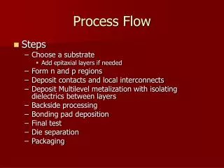
Typical process steps for surface micromachining • modeling and simulation • design a layout • design a mask set thin film formation (by growth or deposition) 1 2 3 4 mask set • This is where process flow becomes complicated. lithography etching die separation release packaging
Mask design and layout • Mask layout • The complete design with all mask layers combined is called the layoutof the device. • Typically use software specifically designed for masks • Program allows you to place mask layers on top of each other to ensure good alignment • Each mask layer shown in a different color and/or line style • The software will separate the layers into the individual masks for fabrication. • The software also keeps track of whether masks should be positive or negative depending on whether the process is typically additive or subtractive
Mask design and layout • Mask alignment • Every mask must have alignment marks that will align the mask to the features on the wafer. alignment feature on mask alignment feature on wafer mask aligned with wafer
Mask design and layout • Mask alignment • Issues to think about when designing the shape and the placement of the alignment mark: • Does the alignment mark shape give wafer orientation as well as alignment? • Asymmetry is good a cross is better than a “plus” • A circular mask opening will produce a square etch in Si showing crystal directions. Align next masks to the square • Make sure your mask does not obscure your alignment mark! • You must be able to see the entire alignment mark through your mask • Dark areas on masks very dark in order to keep light from going through • Features on a wafer tend to be gray • It is good to leave a little “wiggle room” around alignment mark on the wafer
Mask design and layout • Mask alignment • Use a variety of alignment marks • Use one large alignment mark one to get a sense of where you are on the wafer • Use smaller ones to fine tune the alignment • Use several marks on opposite sides of the wafer. A small error in angle can propagate into a large error across the distance of the wafer • Be sure your alignment mark is in a material you can see. • You can see edges in most structural materials and in metals • You cannot see diffusion! • If your first step in the process flow is diffusion, you may need to add another mask to create an alignment mark. Otherwise, you may place the first alignment mark in the first mask you use • First patterning first alignment mark T T T T
Mask design and layout • Mask alignment • Know the process flow of your alignment marks • The process flow of the alignment marks may be different than that of the whole device since the alignment marks see every mask layer and most of your structural/sacrificial layers do not • Does a process step obscure or eliminate an alignment mark you intended to use? (E.g., does a deposited layer covers it up?) If so, you must create another one. • Backside alignment • Backside alignment requires a special “backside aligner” that uses lasers and/or mirror to find the alignment mark on the backside of the wafer.
Surface μ-machined pressure sensor Silicon substrate Poly-Si diaphragm forms one plate of capacitor. n+ diffusion layer forms other “plate” of capacitor Aluminum wires send capacitive electrical signal off the chip. Oxide layer insulates aluminum wires from rest of chip Nitride insulates poly-Si diaphragm from n+ diffusion. Notches to prevent uncompensated stresses from breaking diaphragm during release
Process flow, pass 1 We can go through this example a little quicker. • What are the major steps to create the device? • Diffusion of n+ dopant for bottom “plate” of capacitor • Deposit nitride for electrical insulation • Deposit sacrificial oxide • Add poly-Si diaphragm • Need pedestals and • notches to form diaphragm • Sacrificial etch • Create wires C But isn’t release supposed to be last?
Detailed process flow Mask 2 • Diffusion of n+ dopant for bottom “plate” of capacitor • Note that since we cannot see diffusion we will need to etch alignment marks in the wafer first. • Mask 2 – what does it look like? (Assume positive resist.) • Breakdown of this step: • Etch alignment marks into wafer • Photolithography so that ion implantation only goes where you want it to go • Ion implantation • Remove photoresist • Drive-in • Deposit nitride • No mask is required since it covers the entire wafer Mask 1 is for alignment marks Mask 2
Detailed process flow Mask 3 Mask 4 Mask 5 • Deposit sacrificial oxide • No mask is required since it covers the entire wafer • Why cover the whole wafer? Why not pattern oxide to go just under the diaphragm and nowhere else? • Add poly-Si diaphragm • How do we produce notches and pedestals? • We will need two different etches. • What will our etch stop method be? • Timed etch • Breakdown of this step: • Photolithography notches (Mask?) • Etch notches • Photolithography pedestals (Mask?) • Etch pedestals • Deposit poly-Si • Photolithography poly-Si (Mask?) • Etch poly Mask 3 Mask 4 Mask 5
Detailed process flow Mask 6 Mask 7 • Sacrificial etch • If using oxide for both sacrificial layer and insulation for the wires, need to do sacrificial etch before laying the oxide for the wires. Why? • Contact lithography requires release to be done last. Why? How would we change our process flow if we have to do contact lithography? • Create wires • Deposit oxide • Photolithcontact cuts (mask?) • Etch contact cuts • Deposit Al • Photolith Al (mask?) • Etch Al The height of the features is exaggerated, but the importance of the “depth of focus” idea is very clear. Mask 7 Mask 6
Final process flow • Final Process Flow for Surface Micromachined Pressure Sensor • Starting material: 100mm (100) p-type silicon, 1×1015 cm-3 boron with a 10 mm n-type epilayer, 5×1016 cm-3 phosphorus Clean: Standard RCA cleans with HF dip Photolithography: Mask 1 (alignment) Etch: Etch alignment marks into Silicon. Strip: Strip photoresist Photolithography: Mask 2 (n+ diffusion) Implant: Ion implantation of phosphorous Strip: Strip photoresist Clean: RCA cleans, no HF dip Drive-in: Drive in diffusion Clean: RCA cleans, no HF dip Nitride: Deposit insulating nitride layer Oxide: Deposit sacrificial SiO2 Photolithography: Mask 3 (notches) Etch: Short etch to get notches Strip: Strip photoresist Photolithography: Mask 4 (pedestals) Etch: Longer etch to get pedestals Strip: Strip photoresist Clean: RCA cleans, no HF dip Polysilicon: Deposit polysilicon for diaphragm Photolithography: Mask 5 (diaphragm) Etch: Etch polysilicon Strip: Strip photoresist Sacrificial etch: Remove oxide leaving pedestal Clean: RCA cleans, no HF dip Oxide: Deposit SiO2 for insulation Photolithography: Mask 6 (vias) Etch: Etch oxide to get vias Strip: Strip photoresist Clean: RCA cleans, no HF dip Metal: Deposit aluminum for wires Photolithography: Mask 7 Etch: Etch Aluminum Strip: Strip photoresist Sinter: Anneal contacts
Other issues in process flow • Other issues in designing good process flows • System partitioning: • Whether or not to integrate the MEMS device and any necessary electronics on the same chip • Integration limits MEMS process steps due to temperature, materials, etc. • Process partitioning: • Material used in one process bond with and/or affect the properties of materials in another processes? • If so, the order of the process steps may matter significantly. • Backside processing • Makes many fabrication processes easier, but alignment is more difficult • Also must take into account which steps affect both sides of wafer and which ones affect only one side • Thermal constraints • E.g., photoresist cannot withstand high temperatures, • High temperatures further drive-in dopants
Other issues in process flow • Other issues in designing good process flows • Device geometry • Hard to visualize the 2-D and 3-D aspects of devices Solid-modeling, CAD software developed specifically for MEMS • Combination of conformal deposited layers with directional etching can result in stringers • Can use planarization to avoid stringers, • depth of focus problems, and other issues • arising from large changes in topography stringer An example of a “floating stringer” (Courtesy of Sandia National Laboratory
Other issues in process flow • Other issues in designing good process flows • Mechanical stability: • Fabrication can result in the formation of different stresses in structural layers, causing them to bend or break • Process accuracy: • Expansion or shrinkage of photoresist • Variations in the thickness of layers • Presence of photoresist in structural layers • Mask misalignment between layers C Coming up next! Design rules
Other issues in process flow C A MEMS wheel and hub • If using a wet etchant in step 7 • isotropic or anisotropic C Undercutting
A win-win process flow • The self-aligned gate transistor use poly as electrode and as mask for doping metal electrode poly Si electrode n+ doping virtually no gap increases in switching speed significantly p type wafer overlap causes unwanted increase in capacitance, slower switching speed