Download
1 / 57
580 likes | 821 Views
Introduction to Wireless LAN. Background Media access principle Architecture. MAC control MAC management PHY layer. 802.11 Wireless LAN: Background (15 min). Wireless LANs. Wireless networks today Features and benefits Mobility Flexibility Scalability

E N D
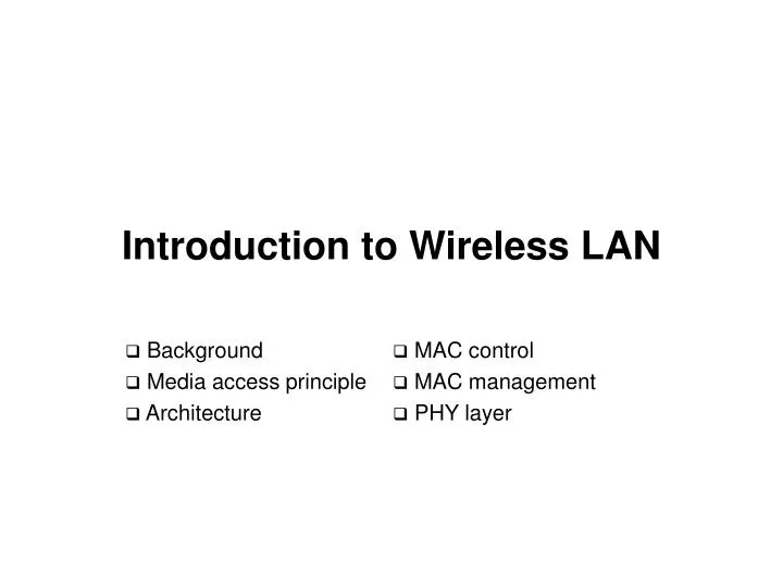
Introduction to Wireless LAN Background Media access principle Architecture • MAC control • MAC management • PHY layer
Wireless LANs • Wireless networks today • Features and benefits • Mobility • Flexibility • Scalability • Wireless LANs: ready now and ready for the future • Standards • Security • Service • Roaming
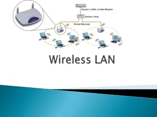
Wireless LAN • Basic Service Set (BSS): a single cell controlled by a Base Station (also called Access Point or AP) • Distribution System: the interconnection network of base stations • Extended Service Set (ESS): the whole interconnected Wireless LAN (seen as a single 802 network), including the different cells, their respective Access Points, and the Distribution System
Radio Frequency In Wireless Networks • Radio spectrum • Narrowband interference • Spread spectrum • FHSS – Frequency Hopping Spread Spectrum • DSSS – Direct Sequence Spread Spectrum • Multi-path interference • IEEE 802.11 series standard • 802.11: 2M • 802.11b: 1M, 2M, 5.4M, 11M • 802.11a: 6M, 9M, 12M, 18M, 24M, 36M, 48M, 54M • 802.11g: compatible with 802.11b and 802.11a • Other standards: • 802.11e: provides Quality of Service (QoS) • 802.11h: supplementary to comply with European regulations • 802.11i: improved WLAN security
Multipath Effect Multipath radio effect. Transmitter signals are reflected or diffracted by structures, changing the signals’ timing, strength, and quality.
IEEE 802.11b Standard 802.11b allows unconnected client devices to communicate with an Ethernet network through an RF (Radio Frequency) transmitter that is physically connected to the wired network.
Deploying Wireless LAN • Ad-hoc network • Association and roaming • Deploying access point and wireless LANs • Deploying access point • Load balancing • Channel selection for neighboring wireless LANs • Multiple channel rate in a wireless LAN US (FCC)/Canada (IC) channel 1 channel 6 channel 11 2400 2412 2437 2462 2483.5 [MHz] 22 MHz
Media Access • Can we apply media access methods from fixed networks? • Example CSMA/CD • Carrier Sense Multiple Access with Collision Detection • send as soon as the medium is free, listen into the medium if a collision occurs (original method in IEEE 802.3) • Problems in wireless networks • signal strength decreases proportional to the square of the distance • the sender would apply CS and CD, but the collisions happen at the receiver • it might be the case that a sender cannot “hear” the collision, i.e., CD does not work • furthermore, CS might not work if, e.g., a terminal is “hidden”
Motivation - hidden and exposed terminals • Hidden terminals • A sends to B, C cannot receive A • C wants to send to B, C senses a “free” medium (CS fails) • collision at B, A cannot receive the collision (CD fails) • A is “hidden” for C • Exposed terminals • B sends to A, C wants to send to another terminal (not A or B) • C has to wait, CS signals a medium in use • but A is outside the radio range of C, therefore waiting is not necessary • C is “exposed” to B A B C
MACA - collision avoidance • MACA (Multiple Access with Collision Avoidance) uses short signaling packets for collision avoidance • RTS (request to send): a sender request the right to send from a receiver with a short RTS packet before it sends a data packet • CTS (clear to send): the receiver grants the right to send as soon as it is ready to receive • Signaling packets contain • sender address • receiver address • packet size • Variants of this method can be found in IEEE802.11 as DFWMAC (Distributed Foundation Wireless MAC)
MACA examples A A C C • MACA avoids the problem of hidden terminals • A and C want to send to B • A sends RTS first • C waits after receiving CTS from B • MACA avoids the problem of exposed terminals • B wants to send to A, C to another terminal • now C does not have to wait for it cannot receive CTS from A RTS CTS CTS B RTS RTS CTS B
Polling mechanisms • If one terminal can be heard by all others, this “central” terminal (a.k.a. base station) can poll all other terminals according to a certain scheme • now all schemes known from fixed networks can be used (typical mainframe - terminal scenario) • Example: Randomly Addressed Polling • base station signals readiness to all mobile terminals • terminals ready to send can now transmit a random number without collision with the help of CDMA or FDMA (the random number can be seen as dynamic address) • the base station now chooses one address for polling from the list of all random numbers (collision if two terminals choose the same address) • the base station acknowledges correct packets and continues polling the next terminal • this cycle starts again after polling all terminals of the list
Comparison: infrastructure vs. ad-hoc networks infrastructure network AP: Access Point AP AP wired network AP ad-hoc network
802.11 - Architecture of an infrastructure network Portal Distribution System • Station (STA) • terminal with access mechanisms to the wireless medium and radio contact to the access point • Basic Service Set (BSS) • group of stations using the same radio frequency • Access Point • station integrated into the wireless LAN and the distribution system • Portal • bridge to other (wired) networks • Distribution System • interconnection network to form one logical network (EES: Extended Service Set) based on several BSS 802.11 LAN 802.x LAN STA1 BSS1 Access Point Access Point ESS BSS2 STA2 STA3 802.11 LAN
802.11 - Architecture of an ad-hoc network • Direct communication within a limited range • Station (STA):terminal with access mechanisms to the wireless medium • Independent Basic Service Set (IBSS):group of stations using the same radio frequency 802.11 LAN STA1 STA3 IBSS1 STA2 IBSS2 STA5 STA4 802.11 LAN
IEEE standard 802.11 fixed terminal mobile terminal infrastructure network access point application application TCP TCP IP IP LLC LLC LLC 802.11 MAC 802.11 MAC 802.3 MAC 802.3 MAC 802.11 PHY 802.11 PHY 802.3 PHY 802.3 PHY
PLCP Physical Layer Convergence Protocol clear channel assessment signal (carrier sense) PMD Physical Medium Dependent modulation, coding PHY Management channel selection, MIB Station Management coordination of all management functions MAC access mechanisms, fragmentation, encryption MAC Management synchronization, roaming, MIB, power management 802.11 - Layers and functions Station Management LLC DLC MAC MAC Management PLCP PHY Management PHY PMD
802.11 - MAC layer I - DFWMAC • Traffic services • Asynchronous Data Service (mandatory) • exchange of data packets based on “best-effort” • support of broadcast and multicast • Time-Bounded Service (optional) • implemented using PCF (Point Coordination Function) • Access methods • DFWMAC-DCF CSMA/CA (mandatory) • collision avoidance via randomized „back-off“ mechanism • minimum distance between consecutive packets • ACK packet for acknowledgements (not for broadcasts) • DFWMAC-DCF w/ RTS/CTS (optional) • Distributed Foundation Wireless MAC • avoids hidden terminal problem • DFWMAC- PCF (optional) • access point polls terminals according to a list
802.11 - MAC layer II • Priorities • defined through different inter frame spaces • no guaranteed, hard priorities • SIFS (Short Inter Frame Spacing) • highest priority, for ACK, CTS, polling response • PIFS (PCF IFS) • medium priority, for time-bounded service using PCF • DIFS (DCF, Distributed Coordination Function IFS) • lowest priority, for asynchronous data service DIFS DIFS PIFS SIFS medium busy contention next frame t direct access if medium is free DIFS
802.11 - CSMA/CA access method I • station ready to send starts sensing the medium (Carrier Sense based on CCA, Clear Channel Assessment) • if the medium is free for the duration of an Inter-Frame Space (IFS), the station can start sending (IFS depends on service type) • if the medium is busy, the station has to wait for a free IFS, then the station must additionally wait a random back-off time (collision avoidance, multiple of slot-time) • if another station occupies the medium during the back-off time of the station, the back-off timer stops (fairness) contention window (randomized back-offmechanism) DIFS DIFS medium busy next frame t direct access if medium is free DIFS slot time
802.11 - competing stations - simple version DIFS DIFS DIFS DIFS boe bor boe bor boe busy station1 boe busy station2 busy station3 boe busy boe bor station4 boe bor boe busy boe bor station5 t medium not idle (frame, ack etc.) busy boe elapsed backoff time packet arrival at MAC bor residual backoff time
802.11 - CSMA/CA access method II • Sending unicast packets • station has to wait for DIFS before sending data • receivers acknowledge at once (after waiting for SIFS) if the packet was received correctly (CRC) • automatic retransmission of data packets in case of transmission errors DIFS data sender SIFS ACK receiver DIFS data other stations t waiting time contention
802.11 - DFWMAC • Sending unicast packets • station can send RTS with reservation parameter after waiting for DIFS (reservation determines amount of time the data packet needs the medium) • acknowledgement via CTS after SIFS by receiver (if ready to receive) • sender can now send data at once, acknowledgement via ACK • other stations store medium reservations distributed via RTS and CTS DIFS RTS data sender SIFS SIFS SIFS CTS ACK receiver DIFS NAV (RTS) data other stations NAV (CTS) t defer access contention
Fragmentation DIFS RTS frag1 frag2 sender SIFS SIFS SIFS SIFS SIFS CTS ACK1 ACK2 receiver NAV (RTS) NAV (CTS) DIFS NAV (frag1) data other stations NAV (ACK1) t contention
DFWMAC-PCF I t0 t1 SuperFrame medium busy PIFS SIFS SIFS D1 D2 point coordinator SIFS SIFS U1 U2 wireless stations stations‘ NAV NAV
DFWMAC-PCF II t2 t3 t4 PIFS SIFS D3 D4 CFend point coordinator SIFS U4 wireless stations stations‘ NAV NAV contention free period t contention period
802.11 - Frame format • Types • control frames, management frames, data frames • Sequence numbers • important against duplicated frames due to lost ACKs • Addresses • receiver, transmitter (physical), BSS identifier, sender (logical) • Miscellaneous • sending time, checksum, frame control, data bytes 2 2 6 6 6 2 6 0-2312 4 Frame Control Duration/ ID Address 1 Address 2 Address 3 Sequence Control Address 4 Data CRC bits 1 1 1 1 1 1 2 2 4 1 1 Protocol version Type Subtype To DS From DS More Frag Retry Power Mgmt More Data WEP Order
MAC address format DS: Distribution System AP: Access Point DA: Destination Address SA: Source Address BSSID: Basic Service Set Identifier RA: Receiver Address TA: Transmitter Address
Special Frames: ACK, RTS, CTS • Acknowledgement • Request To Send • Clear To Send bytes 2 2 6 4 Frame Control Duration Receiver Address CRC ACK bytes 2 2 6 6 4 Frame Control Duration Receiver Address Transmitter Address CRC RTS bytes 2 2 6 4 Frame Control Duration Receiver Address CRC CTS
802.11 - MAC management • Synchronization • try to find a LAN, try to stay within a LAN • timer etc. • Power management • sleep-mode without missing a message • periodic sleep, frame buffering, traffic measurements • Association/Reassociation • integration into a LAN • roaming, i.e. change networks by changing access points • scanning, i.e. active search for a network • MIB - Management Information Base • managing, read, write
Synchronization using a Beacon (infrastructure) beacon interval B B B B access point busy busy busy busy medium t B value of the timestamp beacon frame
Synchronization using a Beacon (ad-hoc) beacon interval B1 B1 station1 B2 B2 station2 busy busy busy busy medium t B value of the timestamp beacon frame random delay
Power management • Idea: switch the transceiver off if not needed • States of a station: sleep and awake • Timing Synchronization Function (TSF) • stations wake up at the same time • Infrastructure • Traffic Indication Map (TIM) • list of unicast receivers transmitted by AP • Delivery Traffic Indication Map (DTIM) • list of broadcast/multicast receivers transmitted by AP • Ad-hoc • Ad-hoc Traffic Indication Map (ATIM) • announcement of receivers by stations buffering frames • more complicated - no central AP • collision of ATIMs possible (scalability?)
Power saving with wake-up patterns (infrastructure) T D awake TIM DTIM data transmission to/from the station B p d broadcast/multicast PS poll TIM interval DTIM interval D B T T d D B access point busy busy busy busy medium p d station t
Power saving with wake-up patterns (ad-hoc) A transmit ATIM ATIM window beacon interval B1 A D B1 station1 B2 B2 a d station2 t B D beacon frame random delay transmit data a d awake acknowledge ATIM acknowledge data
Power Mode of Wireless NIC • Transmit mode • Used during data transmission (sending) • Power consumption: high (e.g., 450mA) • Receive mode • Default mode for both data receiving and listening • Power consumption: medium (e.g., 270mA) • Sleep mode • Power consumption: low (e.g., 15mA)
Power Saving Mechanism • Frame types • Data Frames: used for data transmission • Control Frames: used to control access to the medium • Management Frames: such as Beacon Frame (for synchronization) • The Access Point • maintains a continually updated record of the stations currently working in Power Saving mode • buffers the packets addressed to these stations • periodically transmits information (as part of its Beacon Frames) about which Power Saving Stations have frames buffered at the AP • The Power Saving Station • wake up periodically (100ms) in order to receive the Beacon Frame • if there are frames stored at the AP waiting for delivery, the station stays awake and sends a Polling message to the AP to get these frames • otherwise goes back sleep
Power Consumed during PS Mode Power consumed by Cisco AIR-PCM350 NIC during Power Save Mode Power consumed by Orinoco Gold NIC during Power Save Mode Ecycle(n,t) = 0.060nt + 3300, 0 =< n =< 65535 Ecycle(n,t) = 0.060nt + 3300, 0 =< n =< 65535
Problems • Energy consumption • Wireless networking card consumes a great amount of energy in mobile devices • Over 50% total energy of handheld PC • Up to 10% total energy of laptop PC • Networking performance • Highly depends on the signal strength and transmit power • signal attenuation: distance, obstacles, and environment (humidity, temperature, etc) • transmit power levels: 1mW, 5mW, 20mW, 30mW, 50mW, and 100mW for Cisco Aironet 350 NIC • Latency • Data transmission time: effective bandwidth, loss rate • Mode transition time: power saving mode – normal mode • AP handoff time
802.11 - Roaming • No or bad connection? Then perform: • Scanning • scan the environment, i.e., listen into the medium for beacon signals or send probes into the medium and wait for an answer • Reassociation Request • station sends a request to one or several AP(s) • Reassociation Response • success: AP has answered, station can now participate • failure: continue scanning • AP accepts Reassociation Request • signal the new station to the distribution system • the distribution system updates its data base (i.e., location information) • typically, the distribution system now informs the old AP so it can release resources
802.11 - Physical layer • 3 versions: 2 radio (typ. 2.4 GHz), 1 IR • data rates 1 or 2 Mbit/s • FHSS (Frequency Hopping Spread Spectrum) • spreading, despreading, signal strength, typ. 1 Mbit/s • min. 2.5 frequency hops/s (USA), two-level GFSK modulation • DSSS (Direct Sequence Spread Spectrum) • DBPSK modulation for 1 Mbit/s (Differential Binary Phase Shift Keying), DQPSK for 2 Mbit/s (Differential Quadrature PSK) • preamble and header of a frame is always transmitted with 1 Mbit/s, rest of transmission 1 or 2 Mbit/s • chipping sequence: +1, -1, +1, +1, -1, +1, +1, +1, -1, -1, -1 (Barker code) • max. radiated power 1 W (USA), 100 mW (EU), min. 1mW • Infrared • 850-950 nm, diffuse light, typ. 10 m range • carrier detection, energy detection, synchonization
FHSS PHY packet format • Synchronization • synch with 010101... pattern • SFD (Start Frame Delimiter) • 0000110010111101 start pattern • PLW (PLCP_PDU Length Word) • length of payload incl. 32 bit CRC of payload, PLW < 4096 • PSF (PLCP Signaling Field) • data of payload (1 or 2 Mbit/s) • HEC (Header Error Check) • CRC with x16+x12+x5+1 bits 80 16 12 4 16 variable synchronization SFD PLW PSF HEC payload PLCP preamble PLCP header
DSSS PHY packet format • Synchronization • synch., gain setting, energy detection, frequency offset compensation • SFD (Start Frame Delimiter) • 1111001110100000 • Signal • data rate of the payload (0A: 1 Mbit/s DBPSK; 14: 2 Mbit/s DQPSK) • Service Length • future use, 00: 802.11 compliant length of the payload • HEC (Header Error Check) • protection of signal, service and length, x16+x12+x5+1 bits 128 16 8 8 16 16 variable synchronization SFD signal service length HEC payload PLCP preamble PLCP header
Data rate 1, 2, 5.5, 11 Mbit/s, depending on SNR User data rate max. approx. 6 Mbit/s Transmission range 300m outdoor, 30m indoor Max. data rate ~10m indoor Frequency Free 2.4 GHz ISM-band Security Limited, WEP insecure, SSID Cost 100€ adapter, 250€ base station, dropping Availability Many products, many vendors Connection set-up time Connectionless/always on Quality of Service Typ. Best effort, no guarantees (unless polling is used, limited support in products) Manageability Limited (no automated key distribution, sym. Encryption) Special Advantages/Disadvantages Advantage: many installed systems, lot of experience, available worldwide, free ISM-band, many vendors, integrated in laptops, simple system Disadvantage: heavy interference on ISM-band, no service guarantees, slow relative speed only WLAN: IEEE 802.11b