Download
1 / 26
260 likes | 388 Views
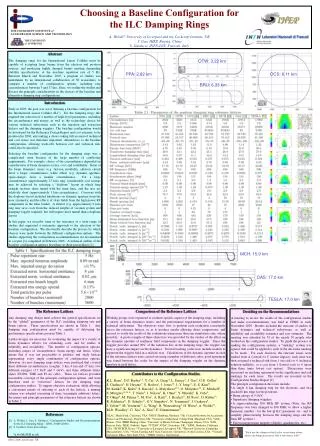
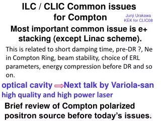
ILC damping rings and common design issues with CLIC. S. Guiducci CLIC09 October 14, 2009. ILC Damping Ring Layout. Two 6.4 km, 5 GeV damping rings are located in a shared tunnel around the interaction region

E N D
ILC damping rings and common design issues with CLIC S. Guiducci CLIC09 October 14, 2009
ILC Damping Ring Layout Two 6.4 km, 5 GeV damping rings are located in a shared tunnel around the interaction region ILC Reference Design Report (RDR) presented at the Beijing GDE Meeting, IHEP, 4-7 February 2007 (http://www.linearcollider.org/cms/)
RDR Lattice Update M. Korostelev
New Baseline SB2009 • DR circumference 6.4 3.2 km • N bunches 2600 1300 • Reducing circumference and number of bunches by keeping the same current keeps the same DR performance and reduces costs • Technical work done for 6 km ring can be applied to 3 km, • similar layout • Nearly same straight sections as DCO4 • arcs based on SuperB-like cells
SB2009 - DSB3 LATTICE STRSECI: INJ/EXTRACTION Inj/Extr 318 m 1000 m 400 m 75% radiation in wigglers 12.5% radiation in this arc RF 8 cavities 42 m 32 wigglers 122 m 12.5% radiation in this arc STRSECR: RF AND WIGGLERS
Common issues • Low Emittance Tuning • Collective effects: • e-cloud • Fast ion • IBS • Impedance related effects • Wiggler dominated ring
Low emittance tuning at CesrTA Objectives Attain sufficiently low vertical emittance to enable exploration of - dependence of electron cloud on emittance - emittance dilution effect of e-cloud • Design/install low emittance optics (1.5 < Ebeam< 5.0 GeV) • Exploit damping wigglers to reduce damping time and emittance • Develop beam-based techniques for characterizing beam position monitors • BPM offsets, Gain mapping, ORM and transverse coupling measurements ==> BPM tilt • Also for measuring and minimizing sources of vertical emittance including • Misalignments • Orbit errors • Focusing errors • Transverse coupling • Vertical dispersion • Develop single bunch/single pass measurements of vertical beam size • Characterize beam current dependence of lifetime in terms of beam size • Measure dependencies of beam size/lifetime on • Beam energy • Bunch current • Species LCWA09 M. Billing
Low Emittance Measurement and Correction I CesrTA Low emittance tuning Orbit A feature of the orbit is the closed horizontal bump required to direct xrays onto x-ray beam size monitor xBSM bump -Measure and correct vertical dispersion using skew quads (14) and vertical steering magnets (~60) Residual vertical dispersion RMS ~ 2.4cm - Signal or systematic? Accuracy of dispersion measurement is limited by BPM systematics v = 2.4 cm RMS Measured with older relay BPM system!! Note: Residual vertical dispersion 1 cm, corresponds to v ~ 10pm LCWA09 M. Billing
CBPM II Modules: V Dispersion After Installation of 80+ CBPM II modules Dispersion Measurement Reproducibility Old Relay BPMs New Digital BPMs Present ev ≤ 40pm Will pursue 20pm with new BPM system during Nov-Dec Experimental run RMS < 0.5 cm LCWA09 M. Billing
Measured Emittance ATF Low Emittance Tuning • - Necessary: a state-of-the-art BPM system, utilizing • a broadband turn-by-turn mode (< 10 µm resolution) • a narrowband mode with high resolution (~ 100 nm range)
e-cloud mitigation 5mm groove tests in KEKB: reduction up to one order of magnitude less cloud current SLAC: PEP-II chamber analysis of TIN surface after 10 years operation New 2mm groove manufactured at KEK. SLAC-KEK design.
Comparisons of EC mitigations: Environments: Drift, Wiggler Chamber Surfaces: Al, Cu, TiN coating, amorphous carbon coating, Cu and TiN-coated Wiggler Chamber Comparisons Mitigation Studies Al VC: Collectors near beam-axis Collectors off beam-axis Amorphous Carbon VC: Collectors near beam-axis Collectors off beam-axis e+ Measurements at CesrTA 8nA/mm2 Full-Scale 10nA/mm2 Full-Scale Cu, 1x45x0.9mA TiN, 1x45x0.9mA
Wiggler: ECLOUD RFA Model Simulations - CesrTA From Joe Calvey Simulation Data Coherent tune shift vs. bunch number e+ data e- data 8/31/2014 LCWA09 18
E-cloud Working Group Charges • To evaluate electron cloud mitigation techniques, simulations and code benchmarking for the Damping Ring. In particular, evaluate the differences between mitigations as grooves clearing electrodes, coating (TiN, TiZrV NEG and amorphous Carbon) regarding their feasibility, effectiveness, impact on the vacuum system, on the beam impedance and on costs, for different regions of the DR as drifts, arc magnets and wigglers. • To recommend a baseline solution for the electron cloud mitigations in the 6.4km (RDR) and 3.2km (SB2009) DR. • Evaluate the ‘upgrade’ potential from the SB2009 proposed 1312 bunches back to the current RDR nominal value of 2623 (doubling the current) immediately identified bottlenecks. • Evaluate the current limits due to e-cloud for the 3.2 km DR. M. Pivi
Fast Ion studies at ATF DR vertical emittance is almost recovered ~< 10 pm. Multi-bunch beam should be well tuned just before the FII study. First step: Re-confirmation of the 2004 results. Then measurements by changing the ionization condition (beam intensity, ion pump ON/OFF, Gas injection, …)
Other collective effects for ILC M. Korostelev
ILC DR wigglers • Extensively used to reduce damping time and emittance and to mitigate IBS effect • CESR-c type superconducting wiggler: good aperture, very good field quality and proven performance. • Number of wigglers 88 • Peak field 1.6 T • Period 0.40 m • Unit length 2.45 m • Vertical aperture 5 cm • Pole width 20 cm
Fast kicker Experiment at ATF Beam kick profile Pulse source(FID FPG 10-6000KN ) Maximum output voltage ±10 kVRise time @ 10-90% level - < 1 nsRise time @ 5-95% level - < 1.2 nsPulse duration @ 90% - 0.2-0.3 nsPulse duration @ 50% - 1.5-2 nsOutput pulse amplitude stability – 0.5-0.7% June beam extraction tests: everything ok but the kick angle was lower than design. To increase the kick angle, we ordered 4ns pulse width pulsers (FPG10-3000N2G) to FID. The total kick angle of two pairs of strip-line is 3.6mrad, enough to extract the beam. Next beam test is scheduled, 2009 Oct. 2weeks(10/19~, 10/26~) T. Naito
Fast kickers in operation at DAFNE fast pulse kck1 kck2 beam hybrid configuration with long and short pulsers e+ beam oscillation with fast kick at DANE (bunch distance 2.7 ns) Measured by diagnostics of the horizontal digital feedback system. 100, of 120, stored bunches with kicker pulse centered on bunch 50
Conclusions • For the ILC DR main issue is e-cloud mitigation: • different tecniques have been demonstrated or are being sperimented • We have setup a working group to apply the results of the R&D to the DR design and make recommendations • ILC DR nominal vertical emittance (2pm) has been demonstrated at Diamond. R&D is needed: • to specify alignment tolerance and stability, and diagnostics requirements. • to demonstrate low emittance at nominal current, taking into account collective effects. • For e-cloud and low emittance issues ILC and CLIC DR have common R&D objectives. • Collaboration on some technical aspects of systems like wigglers, kickers, feedbacks could be useful. • January 12-15 we will have a joint ILC/CLIC DR workshop