Download
1 / 55
570 likes | 721 Views
SOLPS modelling: inputs and outputs, and the connection between. D P Coster , A Chankin, C. Konz, Max Planck Institute for Plasma Physics, EURATOM Association, Garching, Germany February, 2005 Finland. Overview. Model for the edge plasma of a tokamak plasma model SOLPS neutral models

E N D
SOLPS modelling: inputs and outputs, and the connection between D P Coster, A Chankin, C. Konz, Max Planck Institute for Plasma Physics, EURATOM Association, Garching, Germany February, 2005 Finland
Overview • Model for the edge plasma of a tokamak • plasma model • SOLPS • neutral models • surface models • Fitting the experimental measurements • What can be done with the plasma background? • Summary
Inputs • Need as inputs • Equilibrium • Experimental data characterising shot • Upstream profiles of • Te • ne • (Ti) • Target profiles of • Te • ne • Spectroscopic information • Bolometry • Thermography • …
Outputs • Produce as output • Plasma quantities on a grid • Fluxes of particles and energy to surfaces • Simulation of diagnostic signals
And the connection between • Need to vary various things to match the experiment • Model • Fluid neutrals • Automatic procedure for no impurity case • Impurities • Drifts • Boundary conditions • Input heat and particle flux • Pumping • Impurity production • Transport coefficients • Radial profile • Ballooning
Inputs • Need as inputs • Equilibrium • Experimental data characterising shot • Upstream profiles of • Te • ne • (Ti) • Target profiles of • Te • ne • Spectroscopic information • Bolometry • Thermography • …
sep. density (at midplane) controlled input power to grid rad. power monitored neutrals pumping monitored – realistic divertor/ wall geometry SOLPS code, set-up for modelling of ASDEX-U shot #17151 ELMy H-mode with 5 MW of NBI input power Computational grid (48x18, inter- ELM modelling, steady state) Chankin, “SOLPS modelling of ASDEX-U H-mode Plasma”, Edge Physics Forum, Jan 2005 • Plasma description: collisional parallel transp., anomalous perp. coefficients • Neutrals described by EIRENE code (Monte-Carlo) • Physical and chemical sputtering on carbon surfaces included • Drift flows (ExB, B, centrifugal drifts) included, but only in a very few runs
ASDEX-U shot #17151, selected time slice (4.13 s) Chankin, “SOLPS modelling of ASDEX-U H-mode Plasma”, Edge Physics Forum, Jan 2005
Edge/pedestal profiles Elm sync: -5,-0.5 ms ne Te Chankin, “SOLPS modelling of ASDEX-U H-mode Plasma”, Edge Physics Forum, Jan 2005 • Edge Thomson scattering (both ne and Te) and Lithium beam (ne) data • relationship between ne and Te, to be matched by SOLPS • This relationship + constraint on the input power into SOLPS grid determines • choice of separatrix position (if wrong mismatch betweenne and Teat sep.)
And the connection between • Need to vary various things to match the experiment • Model • Fluid neutrals • Automatic procedure for no impurity case • Impurities • Drifts • Boundary conditions • Input heat and particle flux • Pumping • Impurity production • Transport coefficients • Radial profile • Ballooning
Model for the edge plasma of a tokamak • plasma • 2d • fluid • multi-species • neutrals • 2d or 3d • kinetic model or fluid model • material surfaces • plasma streams towards • recycling • sputtering • erosion/deposition • source of neutrals for the plasma
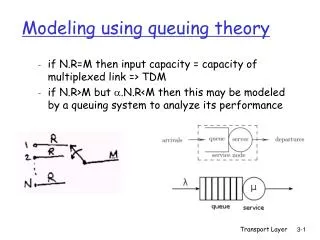
Models for the edge plasma Hierarchy of models • in dimensionality • “two point” models (upstream versus downstream) • 1d • specialist studies • kinetic models (often 1-space, 2 or 3-velocity) • 2d • current “work horses” • one dimension along the field line (parallel), the other “radial” • 3d • specialist studies • stellarators • in development • in physics included • impurities? • atomic physics • self consistency • in “cost” of running
Plasma model for the tokamak edge • Tokamak has toroidal symmetry • usually use 2d approach • Edge plasma usually collisional • fluid approach • with kinetic corrections • much “cheaper” than kinetic approach! • Conservation equations • density of each charge state • parallel momentum of each charge state • electron energy • ion energy • charge AUG
SOLPS: Scrape-Off Layer Plasma Simulation • One of the standard edge codes • (others include UEDGE from Livermore, EDGE2D-NIMBUS from JET) • Suite of codes • Equilibrium Grid • Plasma code • Neutrals code • Plasma+Neutrals Code • Diagnostics Code • Developed over the last 15 years • Used on existing machines (AUG, JET, CMOD, JT60-U, TCV, MAST ...) • For design studies (ITER, SST, HT7U, ...)
Plasma model, II • Processes included • ionisation • charge exchange • recombination • radiation • ... • Transport • (mostly) classical along field lines • anomalous + classical perpendicular to field lines • major uncertainty are the anomalous perpendicular transport coefficients to be used • automatically fitted to experiment • coupling to turbulence codes
Neutral model • Plasma recombines to form neutrals • at surfaces [interaction with solids/or liquids] • in the volume • Neutrals act as sources of particles, momentum and energy for the plasma • Neutrals also interact with material surfaces • Neutrals can be described by one of (or combination of) • fluid model • kinetic model
Neutral model, fluid or kinetic? Ultimately a choice between speed and accuracy
Surface models • Need the surface model to provide • recycling/reflection coefficients (particles and energy) • fixed • TRIM • sputtering coefficients • physical • TRIM • chemical • fixed yield • Roth • ... • any additional sources of particles or energy • sublimation • ...
Surface models, II • In typical runs today, we often assume • carbon arising from sputtering does so as C0 • can use CH4 • higher hydrocarbons are also important • carbon neutrals or ions leaving the plasma “stick” • i.e. zero recycling • To do better, we need • better idea of what mix of hydrocarbons comes off the surface • to improve the hydrocarbon model in the codes • in development at the moment • better idea of sticking/recycling/re-erosion properties for the various hydrocarbons • currently in development in a specialised code • Details of the processes are often first looked at by more specialised codes, then later incorporated (if necessary) in “work horse” codes (e.g. ERO-JET, Jülich)
And the connection between • Need to vary various things to match the experiment • Model • Fluid neutrals • Automatic procedure for no impurity case • Impurities • Drifts • Boundary conditions • Input heat and particle flux • Pumping • Impurity production • Transport coefficients • Radial profile • Ballooning • This process can take a long time! • Days (automatic procedure, fluid neutrals, no impurities) • Weeks (impurities) • Months (impurities, drifts, look at various physics effects)
Outputs • Produce as output • Plasma quantities on a grid • Fluxes of particles and energy to surfaces • Simulation of diagnostic signals
ne, outer midplane Te,Ti, outer midplane SOLPS solution - best fit to experimental profiles Chankin, “SOLPS modelling of ASDEX-U H-mode Plasma”, Edge Physics Forum, Jan 2005 • SOLPS: ne,sep = 1.6x10¹⁹ m-3, Te,sep = 105 eV, Ti,sep = 189 eV, assuming: • - equal sharing of input power into the grid between ion and electron channels • - flux limits set for i/e parallel heat fluxes, 0.3 – for electrons, 1.0 – for ions • - moderate ballooning of transport coefficients (~1/B) • - only Carbon impurity. Phys. sputt. – fixed, Chem.sput.yield – varied to match Prad • - no driftts
ne, outer midplane D,min Transport coefficients – indicate transport barrier inside of sep. Chankin, “SOLPS modelling of ASDEX-U H-mode Plasma”, Edge Physics Forum, Jan 2005 • D has to be reduced to < 0.1 m2/s inside of the separatrix, to describe • measured ne – profile (which is strongly affected by ionisation sources) • Minimum of D and i inside of the separatrix is also obtained for an H- • mode in Hydrogen (#17396, Pin=7.8 MW) (L.D.Horton, IAEA-2004)
Power deposition profiles at outer target Chankin, “SOLPS modelling of ASDEX-U H-mode Plasma”, Edge Physics Forum, Jan 2005 • Langmuir probes give << power than IR camera ( next viewgraph) • SOLPS predicts < power than IR: • - power sharing between divertors outer/inner = 1.57 (non-drift case) • - is raised to 2.87 in a corresponding drift case raises Pout( next viewgraph)
What can the SOLPS output be used for? Verbeek, IPP-Garching, 1997 • Provides a plasma background for more specialised codes • EIRENE (Reiter, Jülich) • to look at charge exchange erosion • opacity effects (photon transport) • pumping • diagnostic interpretation • DIVIMP (Stangeby, Toronto) • to look at tungsten erosion and deposition • direct simulation of some diagnostics • ERO-JET (Kirschner, Jülich) • to try and understand erosion/re-deposition • role of hydrocarbons • ASCOT (Sipila, HUT) • L-H transitions • ion orbit power loss to targets • ... • But all this is predicated on the SOLPS output being a good match to the experiment
Another example: SOLPS impurity modelling • D+12C+13C+He SOLPS (B2-EIRENE) modelling for JET • Attempt to explain C asymmetry • The following don’t work • Transport ballooning • Position of gas puffs • Drifts • Need more
Experimental data: C asymmetry 0.97 12C 13C gas puff 0.99 13C Coad, JNM 2001 Using T as a marker for C migration Strachan, EPS, 2004
Mach number comparisons, II Erents, PPCF, 2004 • Experiment vs SOLPS (drifts + ballooning) • Match (reasonably) drifts • But, still don’t reproduce experimental C asymmetries
13C asymmetry strongly affected • With increasing density, the 13C asymmetry is strongly affected, with most of the 13C appearing at the inner target • The 12C asymmetry increases somewhat, though not to “experimental” levels
Introduce a new recycling model • Nothing we have done seems to have been able to raise the intrinsic C (12C) asymmetry to the experimental levels • Introduce a new recycling model to SOLPS • usually we assume C does not recycle • change so that above a critical temperature, C is assumed to recycle • motivated by ---> “Deposited thickness of C exposed to a plasma containing D+ ions and different amounts of C4+ ions as a function of the plasma temperature. The plasma ion fluence is 1 x 1021 cm-2. The thickness is calculated [...] on the basis of [physical] sputtering yields and reflection coefficients of the pure C [...] materials. Negative values in the ordinate represent net erosion.” [Ohya et al, Physica Scripta Vol 111, 138-144, 2004: fig. 1]
Results of the new model: • For the first time we have been able to see in SOLPS simulations the sorts of asymmetry seen in experiment • [Previous EDGE2D-NIMBUS studies had • added an artificial flow • added a (partly) artificial force • implemented a giant convective cell]
Outputs • Produce as output • Plasma quantities on a grid • Fluxes of particles and energy to surfaces • Simulation of diagnostic signals • Format • Old • fort.30, fort.31, … • Interchange via ftp/e-mail • New • MDSplus tree • Interchange by indicating “shot” number in the MDSplus tree • Further standardisation by EFDA-TF-ITM, hopefully
MDSplus tree: compatible with core ITPA Arne Kallenbach, “Multi-machine divertor database in MDS+ format for inter-machine modelling”, JET TFE Meeting, Lausanne, 19.-21.1.2005
MDSplus tree: extended for Divertor/SOL Arne Kallenbach, “Multi-machine divertor database in MDS+ format for inter-machine modelling”, JET TFE Meeting, Lausanne, 19.-21.1.2005
MDSplus tree: code-exp comparison Arne Kallenbach, “Multi-machine divertor database in MDS+ format for inter-machine modelling”, JET TFE Meeting, Lausanne, 19.-21.1.2005
MDSPLUS used to store SOLPS runs SOLPS [JET, IPP,…] • New postprocessing routine “b2md” • Communicates via TCP/IP • Linux server • 1GB RAM • 2 cpus • Using MR-AFS to provide storage • 11768 shots • 347 GB data • In the Garching DMZ solps-mdsplus. aug.ipp.mpg.de (MDSPLUS server) [Garching] Analysis program (jetdsp, cview, radisplay, idl, matlab) [Fusion Lab] • Any of the standard MDSPLUS experimental plotting programs can be used • Data can be also be accessed via IDL, MATLAB
MDSPLUS SOLPS tree • SOLPS • IDENT: data identifying a run (user, directory, comments, …) • SNAPSHOT: arrays from the end of a run (Te, Ti, ne, …) • TALLIES: time-dependent arrays containing volume and surface integrals (power crossing various surfaces, average densities) • TIMEDEP: time-dependent quantities at positions plus profiles • MOVIE: multiple “snapshots” of Te, Ti, ne ... • DIAG: direct simulation of experimental signals • solps-mdsplus.aug.ipp.mpg.de:8001 • Need to be added to the list of “readers”
Web site contains MySQL index http://solps-mdsplus.aug.ipp.mpg.de/solps
Using IDL/MATLAB to look at SOLPS runs Marco Wischmeier Te R Limiter cases were used by Geier et al to look at W production and migration in AUG using DIVIMP
Conclusions • No real conclusions, but … • Need as much good experimental data as possible to create the “best” plasma background • The “best” plasma background involves a significant effort! • The results of further analysis (ERO, ASCOT, etc.) should be tested by doing a sensitivity study against the plasma background • Important effects might either need to be incorporated into SOLPS or coupled runs performed.
Assumptions/Limitations - Fluid • Fluid treatment of the plasma • kinetic plasma effects not properly treated • Flux limiters • What formulation should we use? • Should we move to ZNC formalism with a equations for heat fluxes and closure at the next higher level? • Should we investigate fluid/kinetic hybrids? • If so, with what priority? • [PIC codes being extended to include recycling --- possibility of improved comparisons] D. P. Coster, X. Bonnin, “ITPA Modeling Assumptions and Limitations”, DIV/SOL November 2004
Assumptions/Limitations – 2D Transport • Transport codes • No 1st principles treatment of radial transport • Radial and poloidal dependence of transport coefficients • Non-diffusive nature (+ pinches) • Parallel transport on a better footing (except for kinetic effects) • 2D • Ignore 3D effects • Erents arguments wrt Mach probe • Localised recycling, sources etc. D. P. Coster, X. Bonnin, “ITPA Modeling Assumptions and Limitations”, DIV/SOL November 2004 Th. Pütterich
Assumptions/Limitations – Limited Domain • Solution domain somewhat limited • Doesn’t extend all the way to the vacuum vessel • What are the appropriate boundary conditions there? • Implications for • heat/particle loads in main vessel • Sources of impurities D. P. Coster, X. Bonnin, “ITPA Modeling Assumptions and Limitations”, DIV/SOL November 2004
Assumptions/Limitations, Neutrals • Neutral treatment • Kinetic: coupling to a Monte-Carlo code • More accurate, slower • Monte-Carlp Noise • Fluid: usually not full Navier-Stokes • Not as accurate • Own temperature? • Still discussion of role of physics • He elastic collisions • Hydrocarbon break up chains • Vibrational excitations • Often details of bypasses, wall out-gassing neglected • Neutral-neutral collisions and optically thick regions D. P. Coster, X. Bonnin, “ITPA Modeling Assumptions and Limitations”, DIV/SOL November 2004
Assumptions/Limitations, Impurities D. P. Coster, X. Bonnin, “ITPA Modeling Assumptions and Limitations”, DIV/SOL November 2004 • Impurities • Intrinsically produced • Somewhat simplified erosion/deposition models • Plasma solution domain usually doesn’t extend to vacuum vessel • Problem with main chamber sources • PSI models usually too simple • Usually not affected by the plasma in the simulations • Heating • Out-gassing/absorption • Isotope exchange • ELM target cooling with Ar at inner target • Hydrocarbon chemistry including T co-deposition • How can we improve them? Th. Pütterich
Assumptions/Limitations, Drifts • Drifts • Still not complete agreement on the equations to be implemented • Not nearly as robust as the non-drift versions • Often have additional time-step limitations • Sometimes have problems with extending to far into the core • Sometimes have problems with reduces solution domain in terms of plasma parameters D. P. Coster, X. Bonnin, “ITPA Modeling Assumptions and Limitations”, DIV/SOL November 2004
Assumptions/Limitations, Drifts D. P. Coster, X. Bonnin, “ITPA Modeling Assumptions and Limitations”, DIV/SOL November 2004 • Time-dependent calculations • Still not that routine • Especially for detailed match to experiment • Comparison of peak power flux density for JET [Subba, EPS-2003]
Assumptions/Limitations, III • Code complexity • Somewhat daunting for someone starting out • Still not that routine to “produce a plasma background” for other purposes • Particularly if drifts are thought to be important for the particular application D. P. Coster, X. Bonnin, “ITPA Modeling Assumptions and Limitations”, DIV/SOL November 2004
H C 1e19 2e19 3e19 4e19 Plasma model, III Transport • flows of impurities can be complicated • affected by • sources • forces in the plasma • affect • pattern of deposition