Download
1 / 28
580 likes | 1.23k Views
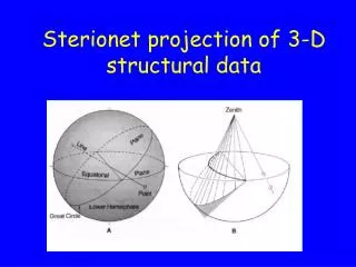
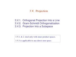
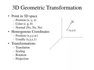
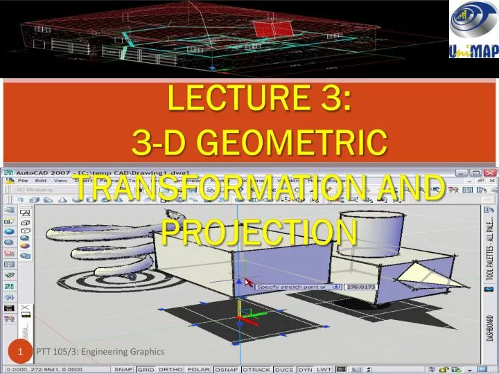
LECTURE 3: 3-D GEOMETRIC TRANSFORMATION AND PROJECTION. TAXONOMY OF PLANAR GEOMETRIC PROJECTIONS. Parallel Projection. Perspective Projection. Orthographic Projection. Projectors are orthogonal to projection surface. Orthographic Projection. Advantages and disadvantages

E N D
LECTURE 3: 3-D GEOMETRIC TRANSFORMATION AND PROJECTION PTT 105/3: Engineering Graphics
TAXONOMY OF PLANAR GEOMETRIC PROJECTIONS PTT 105/3: Engineering Graphics
Parallel Projection PTT 105/3: Engineering Graphics
Perspective Projection PTT 105/3: Engineering Graphics
Orthographic Projection Projectors are orthogonal to projection surface PTT 105/3: Engineering Graphics
Orthographic Projection Advantages and disadvantages • Preserves both distance and angle - shapes are preserved - can be used for measurements: • Building plans • Manufactured parts • Cannot see what object really looks like because many surfaces hidden from view. - often we add the isometric PTT 105/3: Engineering Graphics
Multiview Orthographic Projection • Projection plane parallel to principle face • In CAD and architecture, we often display three multiviews plus isometric. PTT 105/3: Engineering Graphics
Axonometric Projections • Move the projection plane relative to object • Classify by how many angles of a corner of a projected cube are the equal to each other. • Types of axonometric projections: • Three angle equals: isometric • Two angle equals: dimetric • None angle equal: trimetric PTT 105/3: Engineering Graphics
1. ISOMETRIC PROJECTION • The isometricprojection has a standard orientation that makes it the typical projection used in CAD. • In an isometric projection, the width and depth dimensions are sketched at 30° above horizontal. • In an isometric projection all angles between the axonometric axes are equal. • This results in the three angles at the upper front corner of the cube being equal to 120°. • The three sides of the cube are also equal, leading to the term iso (equal) -metric (measure). PTT 105/3: Engineering Graphics
Isometric drawings work quite well for objects of limited depth. • However, an isometric drawing distorts the object when the depth is significant. • In this case, a pictorial perspective drawing is better. PTT 105/3: Engineering Graphics
2. DIMETRIC PROJECTION • In a dimetric projection two of the objects axes make equal angles with the plane of projection and the third angle is larger or smaller than the other two. PTT 105/3: Engineering Graphics
3. TRIMETRIC PROJECTION • In general, the trimetric projection offers more flexibility in orienting the object in space. • In a trimetric projection no two axes make equal angles with the plane of projection. • The width and depth dimensions are at arbitrary angles to the horizontal, and the three angles at the upper front corner of the cube are unequal. PTT 105/3: Engineering Graphics
This makes the three sides of the cube each have a different length as measured in the plane of the drawing; hence the name tri-metric. • In most CAD software, the trimetric projection fixes one side along a horizontal line and tips the cube forward. • Generally, small manufactured objects are adequately represented by isometric or trimetric views. PTT 105/3: Engineering Graphics
Axonometric Projections Advantages and Disadvantages • Lines are scaled (foreshortening) – can find scaling factor but can’t measure distance directly. • Parallel lines preserved but angles are not • Can see three principal faces of box-like object • Some optical illusions possible - parallel lines appear to diverge • Does not look real because far objects are scaled the same as near objects • Used in CAD applications PTT 105/3: Engineering Graphics
Oblique Projection • An OBLIQUE projection is one in which the projectors are other than perpendicular to the plane of projection. • Figure below shows the same object in both orthographic and oblique projections. • The oblique projection: - shows the front surface and the top surface, which includes three dimensions: length, width, and height. Therefore, an oblique projection is one way to show all three dimensions of an object in a single view. PTT 105/3: Engineering Graphics
PERSPECTIVE PROJECTION • A simply perspective (pictorial perspective) projection is drawn so that parallel lines converge towards a single point, unlike isometric or trimetric projections where parallel lines remain parallel. • This has the effect that distant objects appear smaller than nearer objects. • A perspective projection is quite useful in providing a realistic image of an object when the object spans a long distance such as the view of a bridge, railways or aircraft from one end. PTT 105/3: Engineering Graphics
PERSPECTIVE PROJECTION PTT 105/3: Engineering Graphics
Differences between 3D and 2D PTT 105/3: Engineering Graphics
3D Term Frequently Used PTT 105/3: Engineering Graphics
4 types of model used in 3D PTT 105/3: Engineering Graphics
Reasons For Using 3D PTT 105/3: Engineering Graphics
3D Capabilities of AutoCAD PTT 105/3: Engineering Graphics