Download
1 / 29
290 likes | 367 Views
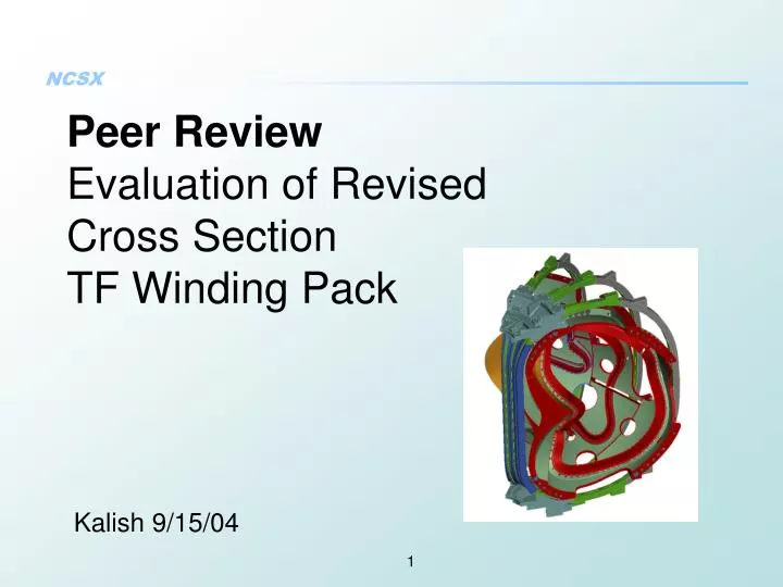
Peer Review Evaluation of Revised Cross Section TF Winding Pack. Kalish 9/15/04. Charge / Outline. Design Evolution and Comparison Analysis Cost / Schedule/ Vendor Impact Design Comparison. Original TF Wedged Winding Pack Cross Section vs New Design. Existing Design. New Design.

E N D
Peer ReviewEvaluation of Revised Cross Section TF Winding Pack Kalish 9/15/04
Charge / Outline • Design Evolution and Comparison • Analysis • Cost / Schedule/ Vendor Impact • Design Comparison
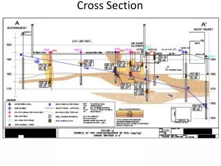
Original TF Wedged Winding Pack Cross Section vs New Design Existing Design New Design Wedge Cut and Reinsulated
Wedge Casting Drawing Tabs on back side of casting top and bottom to resist ejection loads Tabs extend the full length of the casting in front to support wedging loads
Wedging Extends 30 degrees around the upper and lower TF As High as the Upper TF Support Castings
Assembly Supports incase the majority of the TF coil neutralizing the effects of a reduced cross section winding pack
Charge / Outline • Design Evolution and Comparison • Analysis • Cost / Schedule/ Vendor Impact • Design Comparison
Analysis, Stress • Coarse TF stress analysis re-run with modified geometry • Four Load Cases Explored • Stresses and Deflections are adequate for comparative study • Stresses expected to be lower when analysis is repeated with detailed mesh
Stress and Deflection of TF Coil Configurations for Various Load Cases Note: Allowable = 165 MPa
Stress Concentration due toLoss of Support In De-Wedged Region
Force Distribution (.5T Only) Areas with highest loading will be supported by the casting
Casting Provides Support in Critical Area Casting supports and wedges coil 30 degrees around radius supporting area of highest loading Area of Highest Load / Stress
“Ejection Reactions” for Off Normal Load Cases • “Pushers” used to react ejection loads. • Wedge castings add the potential to grab and lock coils top and bottom to react off normal loading.
Analysis / Thermal • Cross sectional area of copper reduced by 31% • Increased Resistance Increases Voltage Requirement falls within the 300V limit to the power supply for first plasma • Temperature rise for original wedged winding pack is only 1.7 K Hydraulic / thermal analysis will be re-run for the reduced cross section. • Restricted Flow can be offset with an increase in pressure • Design point acquired with a dP of 2 psi • Increase of pressure to 38 psi recovers flow • Velocity increases from 1 ft/sec to 4.3 ft/sec
Charge / Outline • Design Evolution and Comparison • Analysis • Cost / Schedule/ Vendor Impact • Design Comparison
Cost of Wedge Castings • Estimate of $2640 per bar from BuyCasting, total of $95,040 for 36 Castings. • addition of 6” length on ends could add $650 per casting set • estimate based on replies from two vendors • In house estimate of $2,900 per casting for straight simpler machined parts backs up casting estimate
Cost Comparison Wedged Winding Packvs Reduced Cross Section With Castings
Effects on Procurement Plan • Reduced Delivery for New Coil Configuration • Coil Delivery reduced by approximately 6 wks due to time saved in machining operation • Time to reinsulate coil offset by time to assemble castings • Advise to use any accelerated delivery to add to contingency, experience with on time delivery of coils is not good • Revised design decreases risk and increases confidence with existing vendor pool but does not increase the number of available coil manufacturers • Vendors contacts do not project confidence in their ability to manufacture a machined wedged winding pack
Charge / Outline • Design Evolution and Comparison • Analysis • Cost / Schedule/ Vendor Impact • Design Comparison
Advantages Lower Risk in the Manufacture of the Coil Lower Risk in obtaining conductor Reduce Stress in Key areas, wedging reacts load at top and bottom Potential to secure structure at top and bottom to resist ejection loads Lower Cost ($92K) Increased Schedule Contingency (6 weeks)Parallel Tasks Disadvantages Additional analysis required Improved stress but not necessarily deflection Break in the middle of the casting to be evaluated Adhesion of Coil to Casting to be verified Increased resistance / higher voltage More Parts Design Comparison