Download
1 / 26
260 likes | 273 Views
This project aims to design and test a high-power plasma generator for the SPL ion source at SLHC. It involves critical components such as a plasma chamber, confinement magnet, ignition source, and RF system. The project also addresses thermal issues and includes simulations and measurements for optimization. The low-level RF system for SPL is also characterized and tested.

E N D
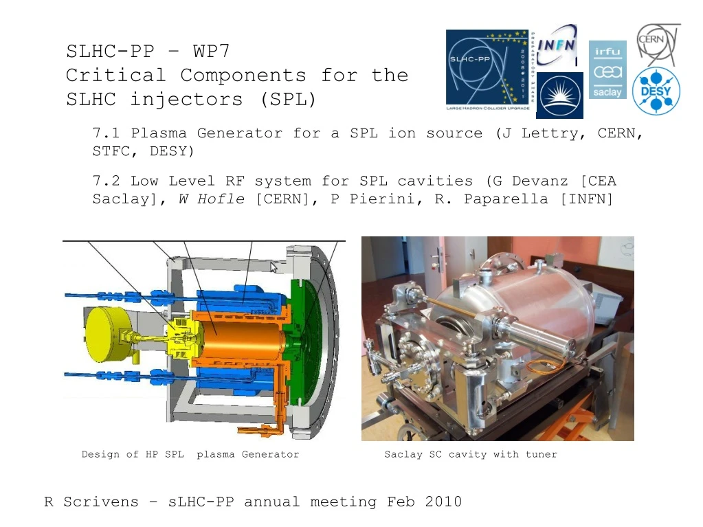
SLHC-PP – WP7 Critical Components for the SLHC injectors (SPL) 7.1 Plasma Generator for a SPL ion source (J Lettry, CERN, STFC, DESY) 7.2 Low Level RF system for SPL cavities (G Devanz [CEA Saclay], W Hofle [CERN], P Pierini, R. Paparella [INFN] Design of HP SPL plasma Generator Saclay SC cavity with tuner
7.1 Plasma Generator for a SPL ion source Create rotationally excited H2 General principle of an RF H- ion source (modified scheme of M. Stockli, SNS) Attach additional electron } Molecule disassociates Multicusp magnets (confinement) ions Inject high power RF (<100kW, 2MHz) Dipolar filter field (remove fast electrons) SLHC-PP Goal: Design and test the plasma generator at high duty factor
SLHC 7.1 meeting January 26th CERN, Room 13-3-05. Comments, summary and conclusions 1) Experimental area Status (JL) 2) Power supply and RF amplifier (David, Mauro) • Remaining power supplies specs should be sent to David. • The average power dissipate by the 2 power racks will be ~ 50 kW • RF amplifier built, interlock by end Feb. (Jose Marquez) • Auto Voltage control (AVC) by end Feb. then tests. • Matching network and insulating Transfo to be designed (we could start with the linac 4 transfo • Remaining spending (2 MHz ampli: 35 kCHF) 3) Status of plasma generator production (December status (JL for Gilles, Didier, Elodie) 4) RF heating of magnets (Dan - Matthias) • Up to 600 A/mm2, 50 W average into10 micron Ni coating up to 150 W/magnet • Cooling mandatory (Cu conducting to heat pipes but its low Mu doesn’t shield B fields) • Demineralized water mu=80 should be included in simulation check other cooling fluids (MK) • Ni saturated, investigate Cu-Ni layer deposition may require round edges. Test required on simple geom.
5) Cusp Magnetic field & Gas injection (Claus) • • Investigate move of permanent magnets outwards and transport of B field via ferrites (CS) • • Check mean free path of electrons P(H2) • • Simulation of new valve compared with old valve measured data 9repeat measurement. All • measurements with one vacuum setup. • 6) Simulation (Liviu) • 7) Draft measurement scheduling (JL) • • Ambitious and optimistic to collect data for the H- conference by September and to allow partial • redesign after intermediate analysis. • 8) linac 4 experimental program (Oystein) • 9) Summary and conclusion (all) • • Meeting in 2 month focused on RF induction on permanent magnets and their cooling • Still on schedule to meet sLHC-PP deliverables.
7.1 Plasma Generator for a SPL ion source Plasma chamber Confinement magnet Ignition source Frame Collar During the project second year: Thermal issues that required solutions were detailed. The plasma generator was completely redesigned in order to include cooling, and mitigate the effects of adding this. It is now partially in production.
Extensive thermal simulations made of the model. Examples of conclusions: Use of AlN as a ceramic (high thermal cond.) Engrave cooling channel into the ceramic (improve thermal contact of water with material) Staggered helical cooling channel. Collar electrodes brazed onto ceramic, on a copper base flange with cooling required.
A dodecapole magnet structure is used for confining the plasma. Inserting a cooling jacket around the chamber moves the magnets outwards, decreasing the srength of the field (no margin to increase the magnet's strength). Solution to use a Holbach-3 magnet design (in order to maintain the same tangential field strength on the chamber inner wall.
Results of measurements of the Linac4 source show higher RF antenna currents. These induce higher currents in the permanent magnets. Produces a high heat load into a critical zone. Additional RF shielding is being investigated as a solution. RF antenna. Current induced into the permanent magnets by the RF antenna.
Test area in preparation, demin water, gas, electricity updated. Vacuum system now installed.
(7.1.3 in M30) Construction of the plasma generator and sub-systems (e.g. 2MHz RF generator, hydrogen gas injection and pumping) (7.1.4 in M36) Plasma generation and study of the thermal and vacuum conditions Tight to make these on time, but still feasible.
7.2 Low level RF for SPL • Characterisation of the CEA, Saclay beta=0.47 cavity and tuner. • Prospects for the INFN cavity and tuner. • SPL RF power layout. • Simulation of low level RF system RF ref
G. Devanz CEA/Saclay Saclay piezo tuner on the beta 0.47 cavity • Planetary gear box (3 stages) • Single NOLIAC 30mm piezo actuator to compensate for Lorentz Force Detuning • Slow tuner with symmetric action • Stiffness measured on the tuner pneumatic jack = 35 kN/mm
G. Devanz CEA/Saclay • The full system : • Beta 0.47 5-cell 704 MHz cavity • 1MW power coupler • Magnetic shield • Piezo tuner Tuner and coupler characterization in cryholab
G. Devanz CEA/Saclay Piezo tuner characterization Beta = 0.47 cavity • Measurement of the cavity tuning offset as a function of tuner parameter • measured at 1.8 K (main tuner parts at 20 K) • piezo 44V for 1 mm elongation of the cavity ( ~2 mm for the piezo actuator) • Maximum detuning measured at 150V DC is 1 kHz • 4.5 K, amplitude = +760kHz corresponding to 2.5 mm -> would be +400 kHz on SPL beta=1 cavity • Mechanical hysteresis measurements will be done at 1.8 K
G. Devanz CEA/Saclay Piezo tuner caracterization Transfer function measurements – Excite cavity mechanical modes with the piezo ? Phase demodulation measurements at 1.8K Transfer Function of piezo drive -> cavity detuning Fcav=703 MHz, far from tuner neutral point for correct piezo pre-load 3 or 4 dominant modes are observed
G. Devanz CEA/Saclay Lorentz force compensation with Saclay piezo tuner Piezo off Field change due to Lorentz force detuning Piezo on - Amplitude excursion now reduced to 1.4% and phase shift within ± 8 deg (not shown) Amplitudes phase Cavity : Eacc=13 MV/m RF: Repetition frequency = 50Hz, pulse length 2ms Measurements using CERN developed LLRF (D. Valuch et al.)
G. Devanz CEA/Saclay Conclusion – Characterisation of first tuner • The mechanical characterization of the piezo tuner and cavity has been carried out. • A Matlab model has been developed in cooperation of the CEA and CERN teams. • Lorentz force detuning compensation at 50Hz demonstrated on the beta 0.47 cavity with the Saclay piezo tuner manually up to 13 MV/m. • The cavity voltage stability is already suitable for a Low Level RF system. • Automatic and optimal compensation is the next step : piezo drive signal synthesis by superposition of simple pulses is foreseen. The systematic measurements to check the validity of this approach just started, an interface from the CERN LLRF system to the piezo drive will be built
P.Pierini, INFN Room temperature test stand - INFN • A special test stand has been equipped at LASA for room temperature evaluation of slow and fast tuning performances Tuning range measurement at warm Test stand elements
P.Pierini, INFN INFN cavity/tuner – Possible Schedule • Warm characterisation of Cavity/Tuner/Motor at INFN. • Cavity/Tuner/Motor transport to CEA • Availability of INFN RF group in supporting preparation, installation and cold measurement is ensured • Details of schedule to be finalized at INFN-MI during meeting with CERN/CEA 15-16/2 • Mainly to agree on list of preparation activities, and sharing of work
Likely choice for high energy part of HPSPL 1 klystron per cavity: individual control possible without RF vector modulator Disadvantage: Many klystrons required Advantage: Easiest for control, considered adopted solution for low energy part In this case and all following cases we assume individual Lorentz-force detuning compensation with a fixed pulse on the piezo or an adaptive feedforward (pulse-to-pulse)
Possible layout for the initial high energy part of LPSPL optional RF vector modulator This case was analyzed, see O. Piquet, CEA Saclay, simulation, LLRF09 workshop Vector modulator Vector modulator Klystron Vector SUM Feedback
Lorentz Force Detuning (2) slope determined by time constant of model stop of RF pulse time offset 1 ms, i.e. 01 ms on left hand side graph detuning negative ! This case (O. Piquet, CEA Saclay, simulation) considerable spread from cavity to cavity to be expected !
Two cavities per klystron high energy part of LPSPL vector sum 10% variation in Lorentz Force detuning KL,1=-2.0 Hz/(MV/m)2 KL,2=-2.2 Hz/(MV/m)2 PI FB controller 5 ms delay in FB loop loop closed at start of beam pulse O. Piquet, CEA Saclay, simulation, LLRF09 workshop
Progress work package 7.2 (1) • Tuner characterization has been re-scheduled during last annual meeting • characterization of CEA Saclay tuning system close to completion • characterization of INFN blade tuner and cavity assembly planned for mid February (warm measurements) at INFN • Report for milestone 7.2.1 • INFN cavity will be transported to CEA Saclay for cold testing at Saclay (vertical cryostat) integration into the “cryholab” for full power tests with nominal coupling and • CEA developed couplers will follow, detailed schedule for INFN cavity to be negotiated during February 2010 meeting at INFN (15.2.-16.2.) • Risk: additional cleaning necessary to reach nominal field for INFN cavity • Testing of CEA Saclay cavity in cryholab continues until completed and INFN cavity ready for power tests at Saclay
Progress work package 7.2 (2) • RF layouts have been presented at the SPL collaboration meeting in November 2009 at CERN, backed up by simulations; optioned narrowed down to • 1 klystron / power amplifier per cavity for the low energy part (low b cavities) • 1 klystron per 1, 2 or 4 cavities investigated for the high energy part • Power requirements estimated for the 1 and 2 cavity per klystron case • 1.5 MW to 1.6 MW power from klystron needed • Simulation model being extended to cover learning algorithm for control of the piezo • Practical experience gained with Lorentz force detuning compensation will be incorporated into the simulation, with the aim to limit the required RF power . • Choices for RF system layout made, report to be produced (7.2.2) , request to re-schedule this milestone as it is late, new date: end June 2010
Progress work package 7.2 (3) • LLRF system development started jointly with CEA • CERN prototype system for Lorentz force detuning measurement implemented and used in the test stand at Saclay on the CEA cavity, next step: hardware modification to control the piezo tuner with this electronics • CEA developed phase feed forward and feedback to keep phase of klystron output constant; analog amplitude loop used, consolidation of these loops into a (I,Q) klystron polar loop being considered for the final demonstrator • CW measurements necessary for calibration purposes (de-tuning calculation), difficult as only a relatively low power (200 W usable) solid state amplifier is available; possible solutions: make Saclay IOT operational; use more sensitive pre-amplifiers for weak cavity antenna signal; more sensitivity is also required to fully record the cavity field decay between pulses at the nominal 50 Hz rate • Implementation of cavity feedback / feed forward after successful control of piezo by CERN electronics • Prototype electronics must be ready by end of August 2010 (M30, 7.2.3) • followed by 6 months to consolidate and validate (M36, 7.2.4)


