Download
1 / 31
310 likes | 325 Views
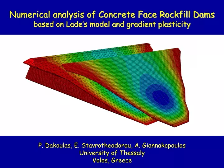
Numerical analysis of Concrete Face Rockfill Dams based on Lade’s model and gradient plasticity. P. Dakoulas, E. Stavrotheodorou, A. Giannakopoulos University of Thessaly Volos, Greece. Motivation:. Realistic prediction of slab performance during impoundment, creep and dynamic settlements.

E N D
Numerical analysis of Concrete Face Rockfill Dams based on Lade’s model and gradient plasticity P. Dakoulas, E. Stavrotheodorou, A. Giannakopoulos University of Thessaly Volos, Greece
Motivation: Realistic prediction of slab performance during impoundment, creep and dynamic settlements Campos Novos Dam Zipingpu Dam
Topics • Behavior and modelling of rockfill • Lade’s constitutive model • A simple gradient plasticity approach • Numerical model • Concrete slab performance: • effect of dam height • effect of rockfill stiffness • Conclusions
Pyramid dam rockfill Oroville dam rockfill average quality excellent quality (Marachi et al. 1972) σ3= 4413 kPa σ3= 4413 kPa 2896 2896 965 965 207 207 σ3=207 kPa σ3=207 kPa 965 965 2896 2896 4413 4413
Lade’s constitutive model for geomaterials yield surface (Dakoulas and Sun 1993) yield surfaces at different levels of plastic work and failure surface stress-strain relationship with hardening and softening behaviour
Lade’s constitutive model for geomaterials The model offers the following advantages: • Continuous variation of the tangent Young’s modulus based on the stress state during the analysis • Realistic description of volumetric strains due to shearing • Realistic handling of the softening behaviour
Simulation of rockfill behavior: isotropic compression (using Lade’s model implemented in ABAQUS as a user material) Oroville rockfill Pyramid rockfill
Possible numerical convergence issues abutment interface Local areas of possible large strain concentration slope surface material zone interface Intense softening behaviour (e.g. due to major rockfill breaking above a critical confining stress, as in Mohale dam) intense softening behaviour
A simple gradient plasticity approach deviatoric plastic strain: gradient coefficient: where: = gradient of = intrinsic length (rockfill size) = reference strain (limit of elastic range) (Bassani 2001)
Numerical models of three dams Dam A material zones 100 m Dam B concrete panels Aspect ratio: L/H = 2 Shape factor: As/H2 = 2.1 200 m
Numerical models of three dams material zones Dam C Aspect ratio: L/H = 2 Shape factor: As/H2 = 2.1 300 m
Numerical modelling of concrete slab panels Geometry: slab width = 15 m slab thickness = 0.30+0.003 h (h = depth of overlying water) Material: Fiber reinforced concrete based on mixing plain concrete with fc= 37 MPa and steel fiber (Reinforcing Index = 2.5%) Uniaxial compression Uniaxial tension
Elastic Young’s modulus at the end of construction H= 200m Elastic Young’s modulus: Oroville rockfill = model parameters = Poisson’s ratio = stress invariants = atmospheric pressure Pyramid rockfill Young’s modulus is derived from unloading test (i.e. purely elastic behavior)
Distribution of settlements at midsection H = 300 m -> S/H = 0.40% H = 300 m -> S/H = 1.47% H = 200 m -> S/H = 0.30% (measured on Oroville dam S/H=0.31%)
Construction settlements narrow canyons
Concrete slab deflection after impoundment H = 200 m Oroville rockfill Pyramid rockfill
Slab deflection after impoundment after long-term creep and dynamic settlements Assumption: Max long-term settlements at crest is 50% of max. construction settlement
Tensile plastic strains in the concrete slab H= 300 m H= 300 m
Compressive stress after impoundment H= 200 m H= 300 m
Compressive stresses after impoundment x H= 200 m y H= 300 m
Compressive stress after long-term settlements H= 200 m H= 300 m
Compressive stresses after long-term settlements x y 3D strength: 57 MPa
Maximum compressive stress vs dam height after impoundment after long-term settlements
Horizontal movement of slab panels after impoundment Oroville rockfill
Horiz. movement of slab panels after long-term settlements Oroville rockfill
CONCLUSIONS • Lade’s model for rockfill allows a realistic simulation of the stress-strain behavior and volumetric strains in a wide range of confining stresses. • Comparison of measured construction settlements of dams in narrow canyons showed good agreement with the numerical predictions of the study. • Use of excellent quality rockfill at void ratios 0.2 allows small construction settlements even for the 300 m dam • Measured slab deflections due to impoundment from 18 CFRDs at various void ratios are in good agreement with the predicted slab deflections
CONCLUSIONS • The use of excellent quality rockfill at void ratios of 0.2 yields small slab deflections even for the 300 m dam during impoundment and long-term settlements • Compressive stresses in the slab reach a maximum at about 40% of the height during impoundment, but may reach a larger value near the crest due to long-term settlements • For the excellent quality rockfill, compressive stresses remain at low levels compared to the strength of concrete • For the average quality rockfill, compressive stresses become very high, especially after long-term settlements • Thank you for your attention!
Acknowledgements This research has been co-financed by the European Union (European Social Fund – ESF) and Greek national funds through the Operational Program "Education and Lifelong Learning" of the National Strategic Reference Framework (NSRF)-Research Funding Program: Heracleitus II. Investing in knowledge society through the European Social Fund.