Download
1 / 13
130 likes | 293 Views
Salt intrusion from top. Vertical cross section. Spatial Discretization. FEFLOW Mesh Generation. Height approx. 100 m. • Automatic mesh generation (~3000 triangular elements) • Mesh refinement (via Rubberbox and Border Options). Model Set-up. FEFLOW Basic Settings.

E N D
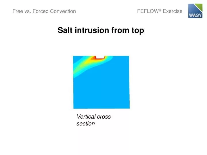
Salt intrusion from top Vertical cross section
Spatial Discretization FEFLOW Mesh Generation Height approx. 100 m •Automatic mesh generation (~3000 triangular elements)• Mesh refinement (via Rubberbox and Border Options)
Model Set-up FEFLOW Basic Settings •2D (default) •Problem Class: Flow and Mass (steady flow, transient transport)•Vertical problem projection•Temporal and control data:Automatic time stepping, FE/BE time integrationFinal time: 36500 days (100 years)
Model Set-up Flow Problem - Material parameters •Global: Density ratioa= 10-3 Input 10[10-4]
Model Set-up Flow Problem - Boundary Conditions •Impermeable border (default)•1st-kind boundary condition at an arbitrary node, e.g., upper left: h = 0 m
Model Set-up Mass-Transport Problem - Boundary Conditions Concentration at the spill site: 100 mg/l Implemented as 1st-kind boundary condition in the center section of the upper border (via Border-Option) •C = 100 mg/l
Numerical Solution FEFLOW Options •Direct equation solver
Numerical Solution FEFLOW Ergebnis Free convection
Model Extension Flow Problem - Boundary Conditions Horizontal hydraulic gradient (‘strong’) Implemented as 1st-kind boundary condition along the left and right vertical borders(via Border-Option): •left side: h = 0 m•right side: h = 0.1 m
Numerical Solution FEFLOW Result Flow is dominated by forced horizontal convection
Model Modification Flow Problem - Boundary Conditions Horizontal hydraulic gradient (‘weak’) Reducing the boundary-condition value on the right vertical border (via Debug option): •right side: h = 0.01 m
Numerical Solution FEFLOW Result Combined effects of free and forced convection