Download
1 / 7
311 likes | 1.98k Views
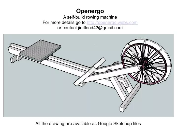
Openergo A self-build rowing machine For more details go to http://openergo.webs.com or contact jimflood42@gmail.com. All the drawing are available as Google Sketchup files. Basic frame structure The parts are fixed together with wood screws. Parts list. C. B. K. J. A (two required).

E N D
Openergo A self-build rowing machine For more details go to http://openergo.webs.com or contact jimflood42@gmail.com All the drawing are available as Google Sketchup files
Basic frame structure The parts are fixed together with wood screws
Parts list C B K J A (two required) D F (two required) L E (two required) G (two required) H
E (two required) Timber parts list Parts A, F and G are from 100mm X 50mm section timber, all the rest are 70mm X 50mm A (two required) F (Two required) G (two required) Cut angles are 60 degrees and 30 degrees unless shown differently End detail of B B Groove for the chain guide D L 42 degree angle K H C J 12 degree angle
Hardware components This plate carries the spindle of the bike wheel and is made from 2mm steel or 3mm aluminium. The slot is cut to fit the spindle. Wheels for the seat – four required, minimum of 50mm diameter. Pulley wheel for the shock cord. About 50mm diameter 26 inch rear bicycle wheel fitted with a small sprocket or gear cassette. 1.5 metres of shock cord (aerolastic). A bicycle wheel inner tube sliced along the length is a good substitute. An 1.8 metre length of bicycle chain to fit the sprocket or cassette fitted on the wheel. This is longer than a standard bike chain so two will need to be joined together. 200mm of 50mm diameter wooden dowel for the handle. This can be carved from square section timber.
Holes drilled at these points for screws to fix the rim to the fan The impeller fan is made from 10mm plywood. With a standard 26 inch bicycle wheel there are nine slots where the spokes are parallel which allow the vanes to fit through. The impeller will need to be adapted to the particular bicycle wheel used. The vanes are screwed and glued to the back plate. Holes are drilled through the rim of the bicycle wheel to fit screws through into the ends of the vanes. The sprocket or gear cassette fits on the opposite side of the fan to the vanes.
The shock cord is attached to the end of the chain by twisting wire around – cover with tape to avoid it catching on edges. The cord runs around the pulley then back to the front of the frame. The chain drive to the impeller Some of the pictures show the impeller fan inside a cover. The cover does not need to be as complicated as the one shown – but a cover is need to protect users from coming into contact with a fast-moving impeller. A free-standing box cover would be okay for this purpose. The handle and chain