Download
1 / 45
450 likes | 567 Views
COMP8700 Agent-Directed Simulation. Introduction to Model Conceptualization and Design. Dr. Levent Yilmaz M&SNet: Auburn M&S Laboratory Computer Science & Software Engineering Auburn University, Auburn, AL 36849 http://www.eng.auburn.edu/~yilmaz.

E N D
COMP8700 Agent-Directed Simulation Introduction to Model Conceptualization and Design Dr. Levent Yilmaz M&SNet: Auburn M&S Laboratory Computer Science & Software Engineering Auburn University, Auburn, AL 36849 http://www.eng.auburn.edu/~yilmaz Acknowledgements: Thanks to Dr. Bernard Zeigler and Dr. Gabriel Wainer for sharing their DEVS lecture materials
Aim • The aim of this lecture is to overview the conventional conceptual and design models as well as fundamentals, principles, and the conceptual framework underlying the DEVS formalism.
Modeling system dynamics Interested in modeling systems’ dynamic behavior ¾ how it organizes itself over time in response to imposed conditions and stimuli. Predict how a system will react to external inputs and proposed structural changes.
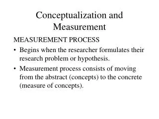
Modeling techniques classification • Conceptual Modeling: informal model. • Communicates the basic nature of the process • Provides a vocabulary for the system (ambiguous) • General description of the system to be modeled
Domain Modeling • Partitions and illustrates the important domain concepts. • A classic object-oriented analysis activity. • What are the objects of interest in the this domain? • their attributes? • their relationships? • IMPORTANT: Not software objects, but a “visual dictionary” of domain concepts.
A Domain Model Does Not Represent Software Objects • A model of domain concepts, not of software objects. • A “visual dictionary” of important words in the domain. • Uses UML static structure diagram notation.
How to Make a Domain Model • List the candidate conceptual classes using the Conceptual Class category list • Draw them in a domain model • Add the associations necessary to record relations • Add the necessary attributes to fulfill the information requirements.
Finding Domain Concepts • Candidate lists (Conceptual category list – textbook page 134) • Linguistic Analysis: Identify the nouns and noun phrases in textual descriptions. • Care must be applied with this method: a mechanical noun-to-class mapping isn’t possible, and words in natural languages are ambiguous. • Specification: Design a library catalog system. The system must support the registration of patrons, checking books in and out patrons, adding and removing of books, and determining which patron has a book.
Approaches • Abbott and Booch suggest: • Use nouns, pronouns, noun phrases to identify objects and classes • Singular object, plural class • Not all nouns are really going to relate to objects • Coad and Yourdon suggest: • Identify individual or group “things” in the system or problem • Ross suggest: • People, places, things, organizations, concepts, events • Danger signs: class name is a verb, is described as performing something
Focus on Important Associations • Use Common associations list (page156 of your textbook) • Name an association based on TypeName – VerbName –TypeName format
Domain Model: Adding Attributes • An attribute is a logical data value of an object. • The values of attributes of an object at any time during run-time execution constitutes the state of that object. • UML Attribute Notation • Relate with associations, NOT attributes
Attributes • Show only “simple” relatively primitive types as attributes. • Connections to other concepts are to be represented as associations, not attributes.
Do Not Use Attributes To Relate Concepts • Why not?
Formal Modeling • Advantage of Formal Methods • Correctness and completeness Testing • Communication means Teamwork • Formalism • Communication convention • Formal specification in unambiguous manner • Abstraction (representation) + Manipulation of abstraction • Formal model - Formal specification
Declarative models • System states (representing system entities) • Transitions between states • State-based declarative models • Example: States = number of persons waiting in line • Transitions: arrival of new customers/departure of serviced ones
Declarative models (cont.) • Event-based declarative models • Arcs: represent scheduling. • Event relation: from arrival of token i to departure of token i.
Functional models • “Black box”. • Input: signal defined over time • Output: depending on the internal function. • Timing delays: discrete or continuous • Example: inputs = customers arriving • Outputs = delayed output of the input customers
Spatial models • Space notions included • Relationship between time and space positions • Example: customers moving through the server.
THE DEVS FORMALISM DEVS = Discrete Event System Specification
Basic Entities and Relations in Modeling and Simulation Experimental Frame Source Simulator System behavior database Modeling Relation Simulation Relation Model
DEVS Modeling & Simulation Framework • DEVS = Discrete Event System Specification • Provides sound formal M&S framework • Supports full range of dynamic system representation capability • Supports hierarchical, modular model development (Zeigler, 1976/84/90/00)
The DEVS Framework for M&S • Separates Modeling from Simulation • Derived from Generic Dynamic Systems Formalism • Includes Continuous and Discrete Time Systems • Provides Well Defined Coupling of Components • Supports • Hierarchical Construction • Stand Alone Testing • Repository Reuse • Enables Provably Correct, Efficient, Event-Based, Distributed Simulation
DEVS Formalism • Discrete-Event formalism: time advances using a continuous time base. • Basic models that can be coupled to build complex simulations. • Abstract simulation mechanism
Atomic model definition Behavioral models
DEVS Atomic models • Atomic DEVS = < S, X, Y, int ,ext , , ta > • X : external input event set • Y : external output event set • S : sequential state set • int: internal transition function • ext :external transition function • : output function • ta : time advance function
DEVS Atomic models (cont.) • ta : S R+0, • Q = {(s,e) | s S, 0 e ta(s)} : total state set, e: elapsed time • int : S S • ext : X * Q X • : S Y S int Y X R ext
Atomic model Discrete Event Dynamics • External Event Transition Function (ext): transforms state and an input event into another state • (e.g., receiving a faulty device, put it into a queue to await its turn for repair.) • Internal Event Transition Function (int): transforms state into another state after time has elapsed • (e.g., there are 10 parts available and broken part requires 7 of them, after fixing broken part, 3 parts will remain.) Time Advance Function (ta): maps a state into a duration (e.g., how long to fix a device once processing has started.) • Output Function (): maps a state into an output • (e.g., number of parts available falls below a minimum number, issue an order to restock.)
DEVS atomic models semantics y (3) x (5) s’ = d ext (s,e,x) (6) l (s) (2) s s’ = d int (s) (4) ta(s) (1) DEVS = < X, S, Y, dint , dext , ta, l >
Atomic model example: ping-pong • AMplayer_A =< S, X, Y, int ,ext , , ta > • X = {Ball_B} • Y = {Ball_A} • S = {A, D} • int (A) = D • ext (Ball_B, D) = A • ta(A) = thinking_time • ta(D) = INFINITY • (A) = Ball_A Ball_A A D Ball_B Ball_B
Dynamic behavior of DEVS models in M out event x1 y1 x2 t S s2=ext((s0,e),x1) s2 s1=int(x2) s1 s0 t e ta(s2) ta(s1) ta(s0) t
Coupled models Structural models (multicomponent)
Hierarchical vs. Incremental modelling G+B+P B+P G P B GEN-BUF-PROC BUF-PROC out in out in out out GEN BUF PROC done A B C Incremental : A andB: connect ABC BC • Petri Net : incremental • DEVS : hierarchical A B C Hierarchical : A and BC: connect
Coupled models formal specification CM = < X, Y, D, {Mi}, {Ii}, {Zij}, select > • Xis the set of input events; • Y is the set of output events; • D is an index for the components of the coupled model, and • " i Î D, Mi is a basic DEVS model (that is, an atomic or coupled model), defined by Mi = < Ii, Xi, Si, Yi, dinti, dexti, tai > • Ii is the set of influencees of model i (that is, the models that can be influenced by outputs of model i), and " j Î Ii, Zijis the i to j translation function. • Finally, select is the tie-breaking selector.
Coupled DEVS example < GEN-BUF-PROC model > out in out in out out GEN BUF PROC done • GEN-BUF-PROC = < X, Y, {GEN, BUF, PROC}, {Ii}, {Zij}, SELECT > • X = ; Y = { out } • I(GEN) = BUF; • I(BUF) = PROC; • I(PROC)= {BUF, self} • Z(GEN)=BUF; Z(BUF)=PROC; • Z(PROC) = BUF; Z(PROC)=self. • SELECT : ({GEN, BUF, PROC}) = GEN ({BUF, PROC}) = BUF
Closure Under Coupling DEVS <X, S, Y, dint,dext, dcon,ta,l > DN <X, Y, D, {Mi }, {Ii },{Zi,j }> Every DEVS coupled model has a DEVS Basic equivalent DEVS <X, S, Y, dint,dext, dcon,ta,l >
Input/output ports concepts start start generator (genr) out repair shop stop repaired faulty sent transducer (transd) report out finished • Components (D) • couplings • Internal Couplings (IC) • External Input Couplings (EIC) • External Output Couplings (EOC)
Coupled DEVS example < GEN-BUF-PROC model > out in out in out out GEN BUF PROC done • GEN-BUF-PROC = < X, Y, {GEN, BUF, PROC}, EIC, EOC, IC, SELECT > • X = • Y = { out } • EIC = • EOC = { (PROC.out, GEN_BUF_PROC.out) } • IC = { (GEN.out, BUF.in), (BUF.out, PROC.in), (PROC.out, BUF.done)} • SELECT : ({GEN, BUF, PROC}) = GEN ({BUF, PROC}) = BUF :
1. nextTN? 3 Output? 5 applyDelt 4 myOut 2. myTN DEVS Simulation Protocol Coupled Model coordinator simulator tN simulator tN simulator tN Component tN tL Component tN tL Component tN tL After each transition tN = t + ta(), tL = t
DEVS Simulator Protocol tL = 0 tN = ta() simulation cycle initialize tL = tN tN = tN + ta() tL = time of last event tN = time of next event