Download
1 / 20
210 likes | 245 Views
Subnetting and Supernetting. Network Prefix and Host number. IP address consists of a network prefix and a host number Prefix notation: 128.100.__.__/16 Notation with netmask: 128.100.__.__ 255.255.0.0. Actual Network Prefix. IP address consists of a network prefix and a host number

E N D
Subnetting and Supernetting
Network Prefix and Host number • IP address consists of a network prefix and a host number • Prefix notation: 128.100.__.__/16 • Notation with netmask: 128.100.__.__255.255.0.0
Actual Network Prefix • IP address consists of a network prefix and a host number • Prefix notation: 128.100.__.__/__ • Notation with netmask: 128.100.__.__255.255.__.__
Subnetting UofT Network • Scenario: Organization has a large network prefix and wants to create smaller networks. • Subnetting: Use a portion of the host name to identify a smaller network (“subnetwork”, “subnet”). • Each subnet becomes a separate network 128.100.0.0/16 Faculty of Engineering Faculty of A&S 128.100.58.0/24 128.100.11.0/24 Library 128.100.136.0/24
Basic Idea of Subnetting • Split the host number portion of an IP address into a subnet number and a (smaller) host number. • Result is a 3-layer hierarchy • Then: • Subnets can be freely assigned within the organization • Internally, subnets are treated as separate networks • Subnet structure is not visible outside the organization network prefix host number network prefix subnet number host number extended network prefix
Subnetmask • Start of the host number is indicated by prefix or netmask notation • The netmask of the extended network prefix is called subnetmask (and the nework is called subnet)
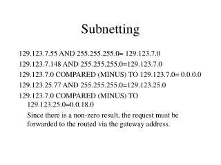
Example • IP address of host: 128.100.11.60 • (original) Network prefix: 128.100.0.0/16 • Subnet number (with length 8 bit) : 11 • Extended network prefix: • Prefix notation: 128.100.11.0/24 • Netmask notation: 128.100.11.0, 255.255.255.0 • Address of host: • Prefix notation: 128.100.11.60/24 • Netmask notation: 128.100.11.60, 255.255.255.0
Advantages of Subnetting • With subnetting, IP addresses use a 3-layer hierarchy: • Network • Subnet • Host • Reduces router complexity. Since external routers do not need to know about subnetting, the complexity of routing tables at external routers is reduced. • Flexibility: Length of the subnet mask need not be identical on all subnetworks.
Creating and Managing Subnets • Use of subnetting or length of the subnetmask is decided by the network administrator • Subnets are created by setting the subnetmask of an IP interface • Important: Subnetmasks must be set consistently
No Subnetting • All hosts think that the other hosts are on the same network
With Subnetting • Hosts with same extended network prefix belong to the same network
With Subnetting • Different subnetmasks lead to different views of the scope of the network
Subnetting and Supernetting • Subnetting: • Subnets are created by extending the network prefix • Supernetting: • Multiple prefixes can be summarized with a single prefix, by reducing the network prefix: 128.143.0.0/16 128.142.0.0/16 128.142.0.0/15 • If neighboring networks have similar address blocks, supernetting reduces the size of routing tables • Route Aggregation: Routing table entries can be reduced, when prefixes can be collapsed and networks have the same outgoing interface
CIDR and Hierarchical IP address allocation • Supernetting helps with reducing size of routing tables: • Backbone ISPs obtain blocks of IP addresses and allocate portions of their address blocks to their customers • Customers can allocate a portion of their address block to their own customers • Note: This leads to a hierarchical organization of networks
Hierarchical Structure of IP Networks Company Y : ISP X owns: 65.10/16 Rest of Internet ISP Z : Organization A: Organization B:
Hierarchical Structure of IP Networks Company Y : 65.11 /16 ISP X owns: 65.10/15 Obtained from ISP X Obtained from ISP X Rest of Internet ISP Z : 65.10/16 Obtained from ARIN Obtained from ISP Z Obtained from ISP Z Organization A: 65.10.11/24 Organization B: 65.10.12/24
Hierarchical Structure of IP Networks Company Y : 65.11/16 ISP X owns: 65.10/15 Routing table entry for 65.11/16 and 65.10/16 (no entry needed for 65.10.11/24 and 65.10.12/24) Rest of Internet ISP Z : 65.10/16 Only one routing entry for 65.10/15No entries needed for network addresses of Company Y, ISP Z, or Organizations A, B. Organization A: 65.10.11/24 Organization B: 65.10.12/24
Drawback of Hierarchical IP Networks • IP address assignment depends on service provider Company Y : 65.11/16 ISP X owns: 65.10/15 Rest of Internet ISP Z : 65.10/16 Must change IP addresses when changing service provider Organization A: 65.10.11/24 Organization B: 65.11.12/24 65.10.12/24
Routing Table Aggregation Routing table entries that can be summarized and that have same outgoing interface can be collapsed. Routing Table
Routing Table Aggregation Routing table entries that can be summarized and that have same outgoing interface can be collapsed. Routing Table