Download
1 / 1
20 likes | 86 Views
Active filter for high order harmonics elimination in traction system. Supervisor Dr:Robin Lisner Associate Supervisor : Prof.:R.E.Morrison. Hany Daoud. Principle of the current injection method. The fundamental principle of this method of reducing

E N D
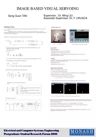
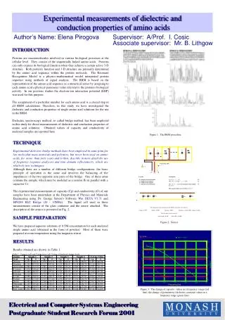
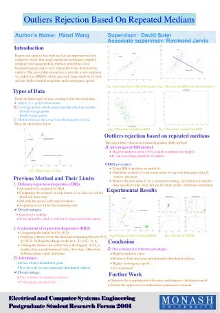
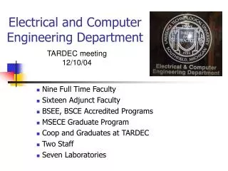
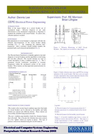
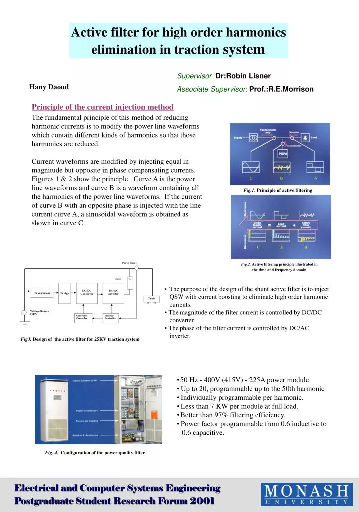
Active filter for high order harmonics elimination in traction system SupervisorDr:Robin Lisner Associate Supervisor: Prof.:R.E.Morrison Hany Daoud Principle of the current injection method The fundamental principle of this method of reducing harmonic currents is to modify the power line waveforms which contain different kinds of harmonics so that those harmonics are reduced. Current waveforms are modified by injecting equal in magnitude but opposite in phase compensating currents. Figures 1 & 2 show the principle. Curve A is the power line waveforms and curve B is a waveform containing all the harmonics of the power line waveforms. If the current of curve B with an opposite phase is injected with the line current curve A, a sinusoidal waveform is obtained as shown in curve C. C B A A C B Fig.1. Principle of active filtering C A B Fig.2. Active filtering principle illustrated in the time and frequency domain. • The purpose of the design of the shunt active filter is to inject • QSW with current boosting to eliminate high order harmonic • currents. • The magnitude of the filter current is controlled by DC/DC • converter. • The phase of the filter current is controlled by DC/AC • inverter. Fig3. Design of the active filter for 25KV traction system • 50 Hz - 400V (415V) - 225A power module • Up to 20, programmable up to the 50th harmonic • Individually programmable per harmonic. • Less than 7 KW per module at full load. • Better than 97% filtering efficiency. • Power factor programmable from 0.6 inductive to • 0.6 capacitive. Fig. 4. Configuration of the power quality filter. Electrical and Computer Systems Engineering Postgraduate Student Research Forum 2001