Download
1 / 38
400 likes | 613 Views
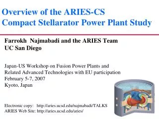
Overview of the ARIES Fusion Power Plant Studies. Farrokh Najmabadi IAEA Technical Committee Meeting on Fusion Power Plant Studies March 24-28, 1998 Culham, United Kingdom. The ARIES Team Has Examined Several Tokamak and non-Tokamak Power Plants in the Past 10 Years.

E N D
Overview of the ARIESFusion Power Plant Studies Farrokh Najmabadi IAEA Technical Committee Meeting on Fusion Power Plant Studies March 24-28, 1998 Culham, United Kingdom
The ARIES Team Has Examined Several Tokamak and non-Tokamak Power Plants in the Past 10 Years • TITAN reversed-field pinch (1988) • ARIES-I first-stability tokamak (1990) • ARIES-III D-3He-fueled tokamak (1991) • ARIES-II and -IV second-stability tokamaks (1992) • Pulsar pulsed-plasma tokamak (1993) • SPPS stellarator (1994) • Starlite study (1995) • ARIES-RS reversed-shear tokamak (1996) • ARIES-ST spherical tokamak (in progress)
Top-Level Requirements for Commercial Fusion Power Plants No public evacuation plan is required: total dose < 1 rem at site boundary; Generated waste can be returned to environment or recycled in less than a few hundred years (not geological time-scale); No disturbance of public’s day-to-day activities; No exposure of workers to a higher risk than other power plants; Closed tritium fuel cycle on site; Ability to operate at partial load conditions (50% of full power); Ability to maintain power core; Ability to operate reliably with less than 0.1 major unscheduled shut-down per year. Above requirements must be achieved consistent with a competitive life-cycle cost of electricity goal. Extra
bA/S ( Plasma b) bp /A ( Bootstrap current fraction) Tokamak Research Has Been Influenced by the Advanced Design Program Current focus of tokamak research “Conventional” high-b tokamaks (Pulsed operation) 2nd Stability high-b tokamaks (Too much bootstrap) Advanced tokamak (Balanced bootstrap) PU: Pulsed Operation SS: 2nd Stability FS: 1st Stability, steady-state RS: Reversed-shear
Engineering Design Options were Assessed Based on High-performance Structural Material Design Class Features Distinct Issues Ferritic Steel Limited efficiency Ceramic or LM breeder Large data base Limited heat flux He, LM, or H2O coolant Large following Ferromagnetism Vanadium-alloy Database/industry Li or ceramic breeder High performance High unit cost He or Li coolant Low afterheat Compatibility Waste disposal Coatings SiC composites Material form& Ceramic breeder Very high performance properties He coolant Excellent safety & High fabrication Waste cost
ARIES-RS Design Emphasized those Features that Maximize Attractiveness • Quantitative goals defined in the form of top-level requirements • Evolved from frequent interaction with customer. • Reversed shear mode of plasma operation: • High b, high bN, high IBS, transport suppression. • High-performance self-cooled lithium with vanadium in high-temperature zones: • Based on ARIES-II with numerous cost-saving measures. • Availability a major engineering trust: • Design for full-sector maintenance with detailed analysis.
Major Parameters of ARIES-RS Design Aspect ratio 4.0 Major toroidal radius (m) 5.5 Plasma minor radius (m) 1.4 Plasma elongation 1.7 Plasma triangularity 0.5 Toroidal b 5% Electron density (1020 m-3) 2.1 ITER-89P scaling multiplier 2.3 Plasma current 11
Major Parameters of ARIES-RS Design Current-drive power to plasma (MW) 81 On-axis toroidal field (T) 8 Peak field at TF coil (T) 16 TF-coil ohmic losses (MW) -- Peak/Avg. neutron wall load (MW/m2) 5.4 / 4 Fusion power (MW) 2,170 Gross electric power (MW) 1,200 Recirculating power fraction 0.17 Cost of electricity (mill/kWeh 76
ARIES-RS is a conceptual 1000MWe power plant based on a Reversed-Shear tokamak plasma
Critical Physics Issues for Advanced Tokamaks • Wall-stabilization of kink modes. • Current drive near plasma edge and especially at mid-plasma. • Current drive power is sensitive to constraint imposed by the divertor: • High separatrix density; • Impurity injection to radiate the plasma energy; • Achieving the necessary density and temperature profiles. • Start-up, access, and
The ARIES-ST Study - Goals & Schedule • The ARIES-ST study is a two-year project to investigate the potential of spherical tokamaks as commercial power plants as well as vehicles for fusion development. • The ARIES-ST study began in Jan. 1997. The effort has been focused on ST power plants. We have emphasized understanding the trade-off and identifying issues that have to be resolved. • The ARIES-ST study will be completed in Fall 1998. The research reported in this meeting represents a progress report as in many areas design work is not completed.
The ARIES-ST Study - Background • Theoretical and experimental studies indicate that the MHD performance of a tokamak plasma is substantially improved with decreasing aspect ratio. • Tokamak power plants with superconducting TF coils, however, tend to optimize at A~ 4 as the gain in b at lower A is offset by gains at higher A through: • Higher on-axis field for a fixed maximum field at the coil; • Lower current-drive power (because of lower plasma current); • Engineering advantages of additional available space. • Question: What is the optimum regime of operation for tokamaks with resistive coils: • for power plants (Joule losses in TF is critical); • for fusion development or non-electric applications (Joule losses in TF may not be as critical).
Key Physics Issues for Spherical Tokamaks • Because of low aspect ratio, the area in the inboard is limited. A resistive TF coil is probably the only option because of the lack of space for a shield for a cryogenic superconducting coil. • In order to minimize the Joule losses in the TF coils (mainly the center-post), MHD equilibria with very high b are required. • Because there is no room for a central solenoid, steady-state operation is mandatory. Because of large plasma current, only MHD equilibria with almost perfect bootstrap alignment would lead to a reasonable current-drive power.
Key Physics Issues for Spherical Tokamaks • Because of unique magnetic topology, on-axis current drive with RF techniques is difficult. Current drive for profile control as well as start-up are additional challenges. • The divertor problem is more difficult than conventional and advanced tokamaks (higher P/R). • Extrapolation of present confinement data base (scaling) to fusion regime is questionable.
Key Engineering Issues for Spherical Tokamaks • The small area available for the inboard legs of the TF coils (center-post) make the design of center-post challenging. • Potential advantages of spherical tokamaks (compact and high wall load) make the engineering of fusion core difficult: • Because of large recirculating power, a highly efficient blanket design is essential; • Water-cooled copper coils further narrow the options; • High heat flux on in-vessel components further narrows the options; • Highly shaped components (tall and thin) make mechanical design difficult. • Maintenance of the power core should include provisions for rapid replacement of center-post.
Spherical Tokamaks Are Quite Sensitive to Physics/Engineering Trade-off • The physics and engineering trade-off are most evident in determining the inboard radial built: • Smaller radial built -> improved plasma performance; • Larger radial built -> engineering credibility; • Every centimeter counts! • Challenge: maximize physics performance while maintaining a credible design.
Major Parameters of ARIES-ST Strawman Aspect ratio 1.6 Major toroidal radius (m) 3.3 Plasma minor radius (m) 2.1 Plasma elongation 3.2 Plasma triangularity 0.57 Toroidal b 35% Electron density (1020 m-3) 3.0 ITER-89P scaling multiplier 2.7 Plasma current 32
Major Parameters of ARIES-ST Strawman Current-drive power to plasma (MW) 57 On-axis toroidal field (T) 2.8 Peak field at TF coil (T) 11.5 TF-coil ohmic losses (MW) 871 Peak/Avg. neutron wall load (MW/m2) 8.2 / 5.4 Fusion power (MW) 4245 Gross electric power (MW) 2204 Recirculating power fraction 0.55 Cost of electricity (mill/kWeh) 111
TF Coil System Is Designed for Vertical Assembly • Water-cooled center-post is made of DS GlidCop AL15. • Outboard TF coil form a shell to minimize mechanical forces. • Center-post is connected to the TF shell through a tapered joint on the top and sliding joints at the bottom. • Insulating joint is located at the outboard mid-plane where the forces are smallest. • Another TF joint is provided for vertical maintenance of the power core.
Vertical Maintenance from the Bottom Is Preferred • Reduced building height & size. • Radioactive material are confined to the maintenance area. • More accurate positioning with lifts compared to cranes.
MHD Equilibrium and Stability • The MHD stability of ST discharges for a wide range of aspect ratio, elongation, triangularity, and kink wall location was examined (with ~ 99% bootstrap fraction). • There is a high leverage to operate at high elongations (and high d) in order to achieve a high b. It appears that operation at k ~ 3 is possible. Detailed work in quantifying the feed-back power necessary for vertical stabilization of high-elongation ST plasmas is on-going. • Low-A free-boundary equilibria is unique and difficult to calculate: • Strong B variation; • Strong plasma shaping (k ~ 3 , d ~ 0.5); • High bp (~2) and low li (~0.15).
Current Drive • High-frequency fast wave (HFFW) can drive the current in the mid-plasma efficiently. • It appears that LFFW is the only plausible RF technique that drives current near the axis on high-b ST plasmas: • Because wpe/ wce >>1, EC and LH waves cannot access the plasma center. • HFFW does not penetrate to the center because of strong electron and/or ion damping; • ICRF fast wave suffer strong electron and a/ion damping. • LFFW requires a large antenna structure for a well-defined spectrum (l||~ 14 m). It generally has a fairly low current-drive efficiency. • We are also exploring NBI as an alternative options.
Divertor • The divertor problem is more difficult than conventional and advanced tokamaks (higher PTR./R ). • To reduce the heat flux to a manageable level, a large fraction of the plasma power has to be radiated: • Radiative mantle; • Impurity radiation in the divertor channel. • Impact of finite edge density and impurities on the MHD/current drive is under investigation. • This approach mainly transfers the divertor problem to the first wall!
Center-post Design -- Inboard Shield • A 20- to 30-cm thick inboard shield is required: • To allow center-post to meet low-level waste disposal requirement; • To reduce nuclear damage to the conductor; • To limit Joule losses due to neutron-induced transmutation; • To reduce nuclear heating in the center-post conductor; • To improve power balance by recovering high grade heat from shield; • To prolong the center-post life time to up to 3 years (same as first wall) in order to minimize impact on availability and replacement cost.
Transmutation of Cu Changes the Center-post Resistivity • Dominant Cu transmutation products are Ni, Zn, and Co • 64Ni and 62Ni dominate the change in resistivity Resistivity changes with a 30-cm, 80% dense Ferritic Steel/He shield
Electrical Design of the Center-post • Leading conductor material is Glidcop AL-15. • It has adequate strength, ductility, low swelling, and thermal and electrical conductivities; • Under irradiation, it suffers from severe embrittlement (at room temperature; • Hardening and embrittlement are alleviated by operating above 180C but then it suffers from severe loss of fracture toughness. • Single-turn TF coils are preferred in order to reduce Joule heating • Higher packing fraction; • Reduced shielding requirement (no insulation); • Requires high-current low-voltage supplies with massive busbars.
Mechanical Design of the Center-post • Sliding electrical joints are employed between center-post and other TF legs and bus-bars and TF legs. • They allow relative motion in radial and vertical directions (which minimizes axial loads on the center-post); • They enhance maintainability; • Several design options have been developed and tested successfully. • Center-post is physically separate from other components in order to avoid a complex interface. • We are currently assessing the degree to which the center-post can be flared to reduce Joule losses.
Thermal-hydraulic Design of the Center-post • Cry-cooling does not offer major improvement over cooling options at room temperature and above. • Water cooling is the leading option:. • Low-temperature operation (Tinlet~ 35C) minimizes Joule losses but results in sever embrittlement of conductor; • High-temperature (Tinlet~ 150 to 180C) avoids embrittlement but lose of fracture toughness and increased Joule losses are key issue.). • Liquid lithium (both conductor and coolant) is probably the best option for high-temperature operation. However, in addition to many challenging engineering issues, recovery of center-post heating does not offset increased Joule losses.
First Wall and Blanket Options • Design which include solid breeders require a major improvement in the thermal conductivity of solid breeders to handle high wall loads.. • Self-cooled Li/V option can handle the high wall load. • The reference blanket design uses ferritic steels as structural material with helium as coolant and LiPb as the liquid breeder. SiC composite fillers are used to achieve a high-coolant outlet temperature and a reasonable power-conversion efficiency.
High-Performance Ferritic Steels Blanket Typically, the coolant outlet temperature is limited to the max. operating temperature of structural material (550oC for ferritic steels) By using a coolant/breeder (LiPb), cooling the structure by He gas, and SiC insulators, a coolant outlet temperature of 700oC is achieved for ARIES-ST increasing the thermal conversion efficiency substantially.
Summary -- ARIES-ST • Several key challenging issues confront spherical tokamaks as fusion power plant. • We have proposed some potential solutions. • Some of these constraints are less sever in a non-electricity producing device. • It appears that spherical tokamak power plants do not offer major improvements over advanced high-aspect ratio tokamaks. • In the remainder of this year, we will complete our reference ARIES-ST design and examine potential of spherical tokamaks as vehicles for fusion development.