Download
1 / 42
420 likes | 431 Views
Network Access Layer: Introduction. Rick Graziani Cabrillo College graziani@cabrillo.edu. Interacts with the network application software. Transforms data into a recognizable format for the application layer. Data/Stream. Controls the dialogues (connections) between devices.

E N D
Network Access Layer: Introduction Rick Graziani Cabrillo College graziani@cabrillo.edu
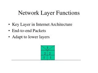
Interacts with the network application software Transforms data into a recognizable format for the application layer Data/Stream Controls the dialogues (connections) between devices Responsible for any reliability, flow control and error control Segment Responsible for message being sent from original sender to final destination Packet Responsible NIC-to-NIC communications on the same network Frame Responsible transmitting the bits over the physical medium (wired or wireless) Bits • Note • These layers and protocols, and the relationship between them will become more evident as you learn about each of the layers and its protocols
Network Interface Cards (NICs) connect a device to the network. • Ethernet NICs are used for a wired connection whereas WLAN (Wireless Local Area Network) NICs are used for wireless.
Network Access Layer: Introduction Rick Graziani Cabrillo College graziani@cabrillo.edu
Physical Layer: Introduction Rick Graziani Cabrillo College graziani@cabrillo.edu
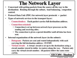
Physical Layer • The OSI physical layer provides the means to transport the bits that make up a data link layer frame across the network media.
Purpose of the Physical LayerPhysical Layer Media • The physical layer produces the representation and groupings of bits for each type of media as: • Copper cable: The signals are patterns of electrical pulses. • Fiber-optic cable: The signals are patterns of light. • Wireless: The signals are patterns of microwave transmissions.
Purpose of the Physical LayerPhysical Layer Standards • Upper OSI layers are performed in software designed by software engineers and computer scientists. • TCP/IP suite are defined by the Internet Engineering Task Force (IETF) in RFCs
Fundamental Principles of Layer 1Physical Layer Fundamental Principles
Fundamental Principles of Layer 1Physical Layer Fundamental Principles • Encoding or line encoding - Method of converting a stream of data bits into a predefined "codes”. • Signaling - The physical layer must generate the electrical, optical, or wireless signals that represent the "1" and "0" on the media.
Physical Layer: Introduction Rick Graziani Cabrillo College graziani@cabrillo.edu
Bandwidth and Throughput Rick Graziani Cabrillo College graziani@cabrillo.edu
Fundamental Principles of Layer 1Bandwidth • Bandwidth is the capacity of a medium to carry data. • Typically measured in kilobits per second (kb/s) or megabits per second (Mb/s).
Fundamental Principles of Layer 1Throughput • Throughput is the measure of the actual transfer of bits across the media over a given period of time limited by latency, delay and other factors. • Due to a number of factors, throughput usually does not match the specified bandwidth in physical layer implementations. • http://www.speedtest.net/ • http://ipv6-test.com/speedtest/
Bandwidth and Throughput Rick Graziani Cabrillo College graziani@cabrillo.edu
Data Link Layer: Introduction Rick Graziani Cabrillo College graziani@cabrillo.edu
The Data Link Layer • NIC to NIC communications on the same network.
Reminder of encapsulation/decapsulation Data Link Trailer Data Link Header IP Header TCP Header HTTP Header Data Data Link Trailer Data Link Trailer Data Link Header Data Link Header IP Packet IP Packet Data Link Trailer Data Link Trailer Data Link Header Data Link Header IP Packet IP Packet Data Link Trailer Data Link Trailer Data Link Header Data Link Header IP Packet IP Packet Data Link Trailer Data Link Header IP Header TCP Header HTTP Header Data
Purpose of the Data Link LayerData Link Sublayers 802.3 Ethernet 802.11 Wi-Fi 802.15 Bluetooth • Data Link layer has two sublayers (sometimes): • Logical Link Control (LLC) – Software processes that provide services to the Network layer protocols (IPv4, IPv6). • Media Access Control (MAC) - Media access processes performed by the hardware. • Provides Data Link layer addressing and framing of the dataaccording to the protocol in use.
Data Link Layer: Introduction Rick Graziani Cabrillo College graziani@cabrillo.edu
Data Link Layer: Accessing the Media Rick Graziani Cabrillo College graziani@cabrillo.edu
Media Access Control • Media Access Control - Regulates the placement of data frames onto the media. • The method of media access control used depends on: • Media sharing • Do more than two nodes share the media? • If so, how? (Switches, hubs, etc.)
Point-to-Point vs multi-access Multi-access Point-to-Point • Point-to-Point networks • Only two nodes • Protocols: PPP, HDLC, Frame Relay • Multi-access networks (LANs) • Multiple nodes • Subnets mask range depends upon the number of hosts (nodes) • Protocols: Ethernet, 802.11 (wireless), Frame Relay Multipoint
Multi-access Topology • A logical multi-access topology - Enables a number of nodes to communicate by using the same shared media. • Ethernet LANs – Connected by Ethernet switches (legacy hubs) • “Every node “may” see all the frames that are on the medium. • Data Link Destination Address denote which device the frame is for.
Multi-access Addressing 4444 6666 2222 3333 5555 • Multi-access networks require an address to specifically identify the destination. • Much more when we discuss Ethernet 6666 2222
Point-to-Point topology 11111111 • A point-to-point topology connects two nodes directly together. • The media access control protocol can be very simple. • Frames from one devices are for the device at the other end. • Point-to-point topologies, with just two interconnected nodes, do not require special addressing.
Data Link Layer: Accessing the Media Rick Graziani Cabrillo College graziani@cabrillo.edu
Full and Half Duplex Rick Graziani Cabrillo College graziani@cabrillo.edu
Duplex Transmissions • Simplex Transmission: One way and one way only. • Half-duplex Transmission: Either way, but only one way at a time. • Ethernet hubs use half-duplex • Full-duplex Transmission: Both ways at the same time. • Ethernet NICs and switches use full-duplex by default • Most serial links are full-duplex • More later with Ethernet
Full and Half Duplex Rick Graziani Cabrillo College graziani@cabrillo.edu
Data Link Layer: Frame Structures Rick Graziani Cabrillo College graziani@cabrillo.edu
Data Link Frame Fields • Data Link frame header fields may include: • Start Frame field - Indicates the beginning of the frame • Source and Destination address fields - Indicates the source and destination nodes on the media • Priority/Quality of Service field - Indicates a particular type of communication service for processing • Type field - Indicates the upper layer service contained in the frame • Logical connection control field - Used to establish a logical connection between nodes • Physical link control field - Used to establish the media link • Flow control field - Used to start and stop traffic over the media • Congestion control field - Indicates congestion in the media
Framing- The Trailer • The signals on the media could be subject to: • Interference • Distortion • Loss • This would change the bit values that those signals represent. • The trailer is used to determine if the frame arrived without error. • Error detection. • The Frame Check Sequence (FCS) field is used to determine if errors occurred in the transmission and reception of the frame.
Cyclic Redundancy Check • Cyclic redundancy check (CRC) is commonly used. • Sending node includes a logical summary of the bits in the frame. • Receiving nodecalculates its own logical summary, or CRC. • Compares the two CRC values. • Equal – Accepts the frame • Different – Discards the frame
Ethernet Protocol for LANs • Ethernet is a family of networking technologies that are defined in the IEEE 802.2 and 802.3 standards. • Uses 48 bit addressing (Ethernet MAC addresses) for Source and Destination • More later!
Point-to-Point Protocol for WANs • Point-to-Point Protocol (PPP) is a protocol used to deliver frames between two nodes.
Wireless Protocol for LANs • 802.11 is an extension of the IEEE 802 standards. • It uses the same 48-bit addressing scheme as other 802 LANs. • Contention-based system using a Carrier Sense Multiple Access/Collision Avoidance (CSMA/CA)
Data Link Layer: Frame Structures Rick Graziani Cabrillo College graziani@cabrillo.edu