Download
1 / 89
940 likes | 1.13k Views
Nuclear power in Japan: Fukushima and after. Richard Tanter Nautilus Institute for Security and Sustainability rtanter@nautilus.org http://www.nautilus.org/about/associates/richard-tanter/publications This PPT at http://www.nautilus.org/about/associates/richard-tanter/talks

E N D
Nuclear power in Japan: Fukushima and after Richard Tanter Nautilus Institute for Security and Sustainability rtanter@nautilus.org http://www.nautilus.org/about/associates/richard-tanter/publications This PPT at http://www.nautilus.org/about/associates/richard-tanter/talks University of Melbourne 19 October 2011
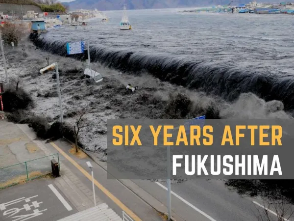
Fukushima I NPP, 2004 Source: Digital Globe, First Watch, Imagery Report, Japan Earthquake/Tsunami, March 2011
Outline • What happened at Fukushima? • What is the situation at Fukushima now? • What will happen from now on? • What have been the health and environmental consequences? • Why did these events occur? • What is the future of nuclear power in Japan? • What are the implications beyond Japan?
Preface • Nuclear power plants: • as a machine • as a socio-technical system • Endemic unsolved issues relevant to all NPPs: • High-level radioactive waste treatment and storage • Operational safety • Nuclear weapon proliferation potential • Post-Fukushima: exposure of workers to resolve loss of coolant accidents • Otherwise, issues specific to particular NPPs and historically specific risk management and operational regimes
A swarm of earthquakes (as of 15 March 2011) Source: United Nations World Food Programme (WFP), “Japan: Earthquakes Swarm (15 Mar 2011),”Relief Web,
Characteristics of Fukushima No. 1 NPP Units 1 - 6 Note: Unit 3 fuel was mixed uranium oxide-plutonium oxide. Source: Report of Japanese Government to the IAEA Ministerial Conference on Nuclear Safety - The Accident at TEPCO's Fukushima Nuclear Power Stations, June 2011, Table IV-1-2.
Fukushima BWR basic design Source: M. Ragheb, Fukushima Earthquake and Tsunami Blackout Accident, 24 June 2011, Figure 21 (from GE and METI)
Unit 1 schematic and inundation level Source: Report of Japanese Government to the IAEA Ministerial Conference on Nuclear Safety - The Accident at TEPCO's Fukushima Nuclear Power Stations, June 2011; Figure III-2-4 (a).
RPV water levels and coolant injection times Source: John H. Large, Update On The Nuclear And Radiological Situation At Fukushima Dai-Ichi, Large & Associates Consulting Engineers, Nr. R3196-AR2, Greenpeace Germany, May 2011; Data source: TEPCO
Unit 1; modelled status of fuel assemblies, melted and slumped Source: Report of Japanese Government to the IAEA Ministerial Conference on Nuclear Safety - The Accident at TEPCO's Fukushima Nuclear Power Stations, June 2011; Attachment IV-!, Reactor Core Conditions of Units 1 to 3 of Fukushima Daiichi Nuclear Power Station, Figure 3.1.9.
Spent fuel at Fukushima I NPP Source: Masa Takubo, cited by David Wright, More on Spent Fuel Pools at Fukushima, All Things Nuclear, March 21, 2010
The proximate source: reactor after-heat following insertion of control rods without cooling = meltdown Source: Jan Beyea and Frank von Hippel, “Containment of a Reactor Meltdown,” Bulletin of the Atomic Scientists, August/September 1982
Unit 4 spent fuel pond - apparently not significantly damaged Source: “No significant damage to fuel at unit 4”, World Nuclear News, 30 April 2011
Key sequences at Fukushima No. 1 NPP: 11 March Pre-quake: • Units 1,2,3 operating; • Units 5 and 6 offline in cold shutdown; • Unit 4 offline; defueled November 2010 14.46 Magnitude 9 earthquake 135 km offshore • Automatic shutdown of Units 1,2, and 3. • Offsite power is lost. • Emergency diesel generators (EDGs) provide coolant power 15.46 14 metre-tsunami breaches plant seawalls and inundates most of the plant • Emergency generators flooded and short-circuited • Battery powered pumping system starts; fails by March 12. 19.30 Fuel assemblies in Unit 1 completely exposed
Station blackout accident: Reactor Core Isolation Cooling System failed with loss off-site and emergency AC power and DC battery power • Off-site power lost in earthquake due to damage to a transformer 10 kms from NPP • 13 emergency diesel generators each “the size of a locomotive”, each 6 MWhr capacity • 8 in the basement of the main turbine hall, two at ground level behind Unit 4 • 12/13 disabled by the tsunami • Batteries supplying DC power exhausted after 9-12 hours
Key sequences at Fukushima No. 1 NPP: 12 - 15 March • Oxidation of zirconium cladding by steam → hydrogen • Zr + 2 H2O → ZrO2 + 2 H2 • March 12: • 15.36 Unit 1 hydrogen explosion destroys upper structure exposing fuel pond; 4 workers injured • March 14 • 11.01 Unit 3 hydrogen explosion destroys upper structure exposing fuel pond; 6 workers injured • March 15 • Fire at Unit 4 spent fuel pond • Hydrogen explosion in Unit 2; suspected damage to wet-well in primary containment. • Explosion at Unit 4 spent fuel pond: origin possibly Unit 3 RPV
Decay curves of short-lived and long-lived isotopes Source: M. Ragheb, Fukushima Earthquake and Tsunami Blackout Accident, 24 June 2011, Fig. 26.
Long half-life fission isotopes Source: M. Ragheb, Fukushima Earthquake and Tsunami Blackout Accident, 24 June 2011.
Japanese government report to IAEA: Fukushima “worse than meltdown?” Source: “'Melt-through' at Fukushima? / Govt report to IAEA suggests situation worse than meltdown”, Yomiuri Shimbun, 8 June 2011.
Fukushima I NPP, 2004 Source: Digital Globe, First Watch, Imagery Report, Japan Earthquake/Tsunami, March 2011
Seawater pump - March 17 Source: Fukushima Daiichi Nuclear Power Station Photos 16, Cryptome.org
Flooded electric equipment room, Unit 6, March 17 Source: Fukushima Daiichi Nuclear Power Station Photos 16, Cryptome.org
State of Fukushima No. 1 NPP, as of 14 October:a. reactors and spent fuel Source: Status of countermeasures for restoring from the accident at Fukushima Daiichi Unit 1 through 4. As of October 14th, 2011. (Estimated by JAIF)
State of Fukushima No. 1 NPP, as of 14 October:b. contaminated water leakage and water storage • Contamination of huge volumes of sea-water and freshwater injected and sprayed into containment buildings and spent fuel ponds • Some released to sea • Most stored onsite in turbine building basement, etc. • Some stored on floating barges • Highly radioactive leakages from damaged reactor pressure vessels and containment vessels • into sea and into groundwater
State of Fukushima No. 1 NPP, as of August 30:c. Site debris and contamination Source: TEPCO, Survey map of Fukushima Daiichi Nuclear Power Station, August 22, 2011.
Key current site operations • Heat exchange of cooling water to CPV/RPV • Decontamination of radioactive water in containment vessel, in flooded areas, and in storage • As of 9 August, 42,000 tonnes processed, but 120,000 tonnes remained on site; expected end-year goal of 200,000 tonnes now unlikely • Reducing/eliminating onsite radioactive hotspots • Covering all four units with steel and plastic to reduce air-borne contamination
Cold Shutdown Process Behind Schedule Source: Fukushima Cold Shutdown Process Behind Schedule, NikkeiNet, 17 August 2011
3. What will happen from now on? • Units 1-4 to be decommissioned; Units 5-6 unclear • New TEPCO “roadmap” presented to JAEC 31 August • Plastic covering for Units 1-4 to contain airborne radiation matter • Cold shut down by January 2012 ….? • By end-2011 will start building ground shield between Units 1-4 and sea • 800 metres long and 20 metres deep • possible extension around whole of Units 1-4 • Removal of fuel from spent fuel ponds 1-4 • Removal of spent fuel from reactors 1-4 • Removal of corium from Units 1,2 and 3 - from RPV and/or CPV • 10-50 years before attempt at reactor/corium removal possible • Decontamination, dismantling and clean-up …. Sometime in the future …
The TEPCO roadmap (as of 17 August 2011) • Basic objective: reactors and nuclear fuel ponds to a stable condition and mitigating release of radioactive materials. • Step 2: • Control of release of radioactive materials • Accelerate processing of water to reduce required volume • then increase rate of water injection by continuous and reinforced circulating injection cooling towards cold shutdown. Source: Summary of Progress Status of Roadmap towards Restoration from the Accident at Fukushima Daichi NPP TEPCO, National Nuclear Response Headquarters, 17 August 2011.
TEPCO: roadmap implementation “issues” • Reactors: confirm functional securiting of water injection system • SFP: more stable cooling • Accelerate water treatment • Groundwater: design shield • Atmosphere/soil - steel/plastic covering • Measurement of radiation and disclosure • Tsunami reinforcement for Unit 4 SNP • Living/working environment • Radiation control/medical care • Staff training Source: Summary of Progress Status of Roadmap towards Restoration from the Accident at Fukushima Daichi NPP TEPCO, National Nuclear Response Headquarters, 17 August 2011.
Model of plastic coverage for Unit 1 Source: TEPCO, Attachment,Outline of the reactor building covering plan of Unit 1 at Fukushima Daiichi Nuclear Power Station, Press Release
Unit 1 plastic cover: before and after Source: TEPCO, Attachment, Outline of the reactor building covering plan of Unit 1 at Fukushima Daiichi Nuclear Power Station, Press Release
Seaward-side water shield plan Source: TEPCO, Attachment, Basic Design of Water Shield Wall at the Seaside, Press Release 31 August 2011, p. 6.
Seaward-side water shield - schematic cross-section(piles: 1 metre diameter, 14-22 mm. thick, 22-23 metres deep) Source: TEPCO, Attachment, Basic Design of Water Shield Wall at the Seaside, Press Release 31 August 2011, p. 6.
Fukushima No.1 NPP hydrology (pre-quake data) Source: TEPCO, Attachment, Basic Design of Water Shield Wall at the Seaside, Press Release 31 August 2011, p. 7.
Cross-section of hydrology model (pre-quake data) Source: TEPCO, Attachment, Basic Design of Water Shield Wall at the Seaside, Press Release 31 August 2011, p. 7.
Underground water trajectory modelling schematic Source: TEPCO, Attachment, Basic Design of Water Shield Wall at the Seaside, Press Release 31 August 2011, p. 8.
Anticipated underground water levels with seaside-ward water shield in place Source: TEPCO, Attachment, Basic Design of Water Shield Wall at the Seaside, Press Release 31 August 2011, p. 8.
The corium issue • Corium = the liquid or solid slag within or below the reactor pressure vessel (RPV) resulting from a melting of fuel rods, cladding, steel structures, and subsequent chemical reactions and physical events • If the corium melts through the steel RPV to the concrete base-mat of the primary containment vessel (PC or PCV), corium-concrete chemical reactions may include gases including CO, CO2, H2 • There is a further possibility of corium passing through the base-mat if the PCV is ruptured (e.g. by H2 explosion) or if melted by the corium
Debris bed from core melting at Three Mile Island NPP Source: M. Ragheb, Fukushima Earthquake and Tsunami Blackout Accident, 24 June 2011, Figure 43.
Fukushima BWR basic design Source: M. Ragheb, Fukushima Earthquake and Tsunami Blackout Accident, 24 June 2011, Figure 21 (from GE and METI)