Download
1 / 22
240 likes | 386 Views
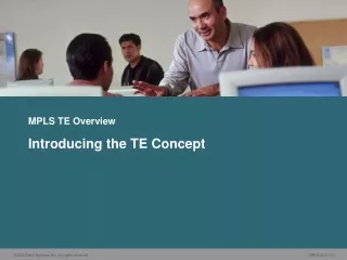
MPLS TE Overview. Understanding MPLS TE Components. Outline. Overview Traffic Tunnels: Concepts Traffic Tunnels: Characteristics Traffic Tunnels: Attributes Network Links and Link Attributes Constraint-Based Path Computation TE Processes

E N D
MPLS TE Overview Understanding MPLS TE Components
Outline • Overview • Traffic Tunnels: Concepts • Traffic Tunnels: Characteristics • Traffic Tunnels: Attributes • Network Links and Link Attributes • Constraint-Based Path Computation • TE Processes • Role of RSVP in Path Setup and Trunk Admission Control • Forwarding Traffic to a Tunnel • Summary
Traffic Tunnels: Concepts • The concept of MPLS TE traffic tunnels was introduced to overcome the limitations of hop-by-hop IP routing: • A tunnel is an aggregation of traffic flows that are placed inside a common MPLS label-switched path. • Flows are then forwarded along a common path within a network.
Traffic Tunnels: Concepts (Cont.) • Unidirectional single class of service modelencapsulates all of the traffic between an ingress and an egress router. • Different classes of service model assigns traffic into separate tunnels with different characteristics.
Traffic Tunnels – Characteristics • A traffic tunnel is distinct from the MPLS LSP through which it traverses: • More than one TE tunnel can be defined between two points: • Each tunnel may pick the same or different paths through the network • Each tunnel will use different MPLS labels • A traffic tunnel can be moved from one path onto another based on resources in the network. • A traffic tunnel is configured by defining its required attributes and characteristics.
Traffic Tunnels – Attributes • Attributes are explicitly assigned through administrative action. • A traffic tunnel is characterized by: • Its ingress (headend) and egress (tailend) label switch routers • The forwarding equivalence class that is mapped onto it • A set of attributes that determine its characteristics
Traffic Tunnels–Attributes (Cont.) • The administrator enters the relevant information (attributes) at the headend of the traffic tunnel: • Traffic parameter—Resources required for tunnel (for example, required bandwidth) • Generic path selection and management—Path can be administratively specified or computed by the IGP • Resource class affinity—Include or exclude certain links for certain traffic tunnels • Adaptability—Should the traffic tunnel be reoptimized? • Priority and preemption—Importance of a traffic tunnel and possibility for a preemption of another tunnel • Resilience—Desired behavior under fault conditions
Network Links and Link Attributes • Resource attributes (link availability) are configured locally on the router interfaces: • Maximum bandwidth • The amount of bandwidth available • Link affinitystring • To allow the operator to administratively include or exclude links in path calculations • Constraint-based specific metric • TE default metric
Constraint-Based Path Computation • Constraint-based routing is demand-driven. • Resource-reservation-aware routing paradigm: • Based on criteria including, but not limited to, network topology • Calculated at the edge of a network: • Modified Dijkstra’s algorithm at tunnel headend (CSPF [Constraint-based SPF] or PCALC [path calculation]). • Output is a sequence of IP interface addresses (next-hop routers) between tunnel endpoints.
Constraint-Based Path Computation (Cont.) • Constraint-based routing takes into account: • Policy constraints associated with the tunnel and physical links • Physical resource availability • Network topology state • Two types of tunnels can be established across those links with matching attributes: • Dynamic—Using the least-cost path computed by OSPF or IS-IS • Explicit—Definition of a path by using Cisco IOS configuration commands
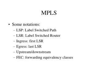
Traffic Engineering Processes • Information distribution • Path selection and calculation • Path setup • Trunk admission control • Forwarding traffic on to tunnel • Path maintenance
Role of RSVP in Path Setup Procedures • When the path has been determined, a signaling protocol is needed: • To establish and maintain label-switched paths (LSPs) for traffic tunnels • For creating and maintaining resource reservation states across a network (bandwidth allocation) • The Resource Reservation Protocol (RSVP) was adopted by the MPLS workgroup of the IETF.
Path Setup with RSVP • When the path has been calculated, it must be signaled across the network. • Reserve any bandwidth to avoid “double booking” from other TE reservations. • Priority can be used to preempt low priority existing tunnels. • RSVP is used to set up TE LSP. • PATH message (from head to tail) carries LABEL_REQUEST. • RESV message (from tail to head) carries LABEL. • When RESV messages reaches headend, tunnel interface is up. • RSVP messages exist for LSP teardown and error signaling.
RSVP and Trunk Admission Control • On receipt of PATH message: • Router checks whether there is bandwidth available to honor the reservation. • If bandwidth is available, then RSVP is accepted. • On receipt of a RESV message: • Router actually reserves the bandwidth for the TE LSP. • If preemption is required, lower priority LSPs are torn down. • OSPF or IS-IS updates are triggered.
Forwarding Traffic to a Tunnel • IP routing is separate from LSP routing and does not see internal details of the LSP. • The traffic has to be mapped to the tunnel: • Static routing—The static route in the IP routing table points to an LSP tunnel interface. • Policy routing—The next-hop interface is an LSP tunnel. • Autoroute—SPF enhancement: • The headend sees the tunnel as a directly connected interface (for modified SPF only). • The default cost of a tunnel is equal to the shortest IGP metric regardless of the used path.
IP Forwarding Database Modification with Autoroute • Autoroute feature enables the headend to see the LSP as a directly connected interface: • This feature is used only for the SPF route determination, not for the constraint-based path computation. • All traffic directed to prefixes topologically behind the tunnel endpoint (tailend) is forwarded onto the tunnel. • Autoroute affects the headend only; other routers on the LSP path do not see the tunnel. • Tunnel is treated as a directly connected link to the tailend: • When tunnel tail is seen in PATH list during IGP SPF, replace outgoing physical interface with tunnel interface. • Inherit tunnel to all downstream neighbors of tailend.
Tunnel1: R1 R2 R3 R4 R5 Tunnel2: R1 R6 R7 R4 Autoroute Topology (OSPF and ISIS)
Autoroute Topology (OSPF and ISIS) From R1 Router Perspective: Next hop to R5 is Tunnel1. Next hop to R4 and R8 is Tunnel2. All nodes behind tunnel are routed via tunnel. 20 20
Summary • Traffic tunnels are configured with a set of resource requirements, such as bandwidth and priority. • CSPF augments the link cost by considering other factors such as bandwidth availability or link latency when choosing a path. • RSVP with TE extensions is used for establishing and maintaining LSPs. • TE tunnels do not appear in the IP routing table.